Jet pump for internal-combustion engine and internal-combustion engine having the jet pump

A technology for injection pumps and internal combustion engines, applied in the fields of injection pumps and internal combustion engines, which can solve problems such as suction hole damage and corrosion

Inactive Publication Date: 2009-12-16
MAN ENERGY SOLUTIONS SA
View PDF2 Cites 0 Cited by
  • Summary
  • Abstract
  • Description
  • Claims
  • Application Information

AI Technical Summary

Problems solved by technology

This cavitation (Kavitation) can lead to damage to the suction hole, especially to corrosion

Method used


Image

  • Jet pump for internal-combustion engine and internal-combustion engine having the jet pump
  • Jet pump for internal-combustion engine and internal-combustion engine having the jet pump
  • Jet pump for internal-combustion engine and internal-combustion engine having the jet pump

Examples


Embodiment Construction

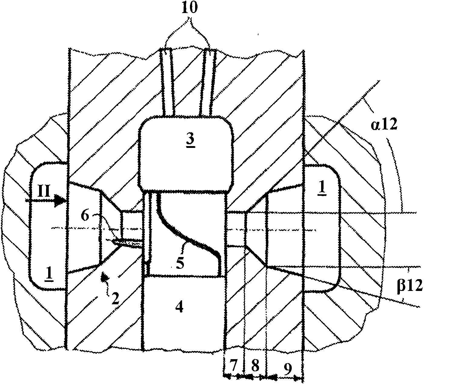
[0048] figure 1 Shown in axial section is a part of an injection pump for an internal combustion engine (not shown) according to an embodiment of the invention, the injection pump having a suction chamber 1 which is distributed by means of a pre-delivery system (not shown) with fuel under high pressure. The injection pump also has a high-pressure chamber 3 in which fuel is brought under injection pressure via a piston 4 and delivered via a line 10 to a combustion chamber of an internal combustion engine (not shown).

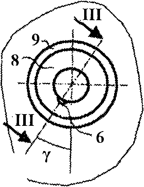
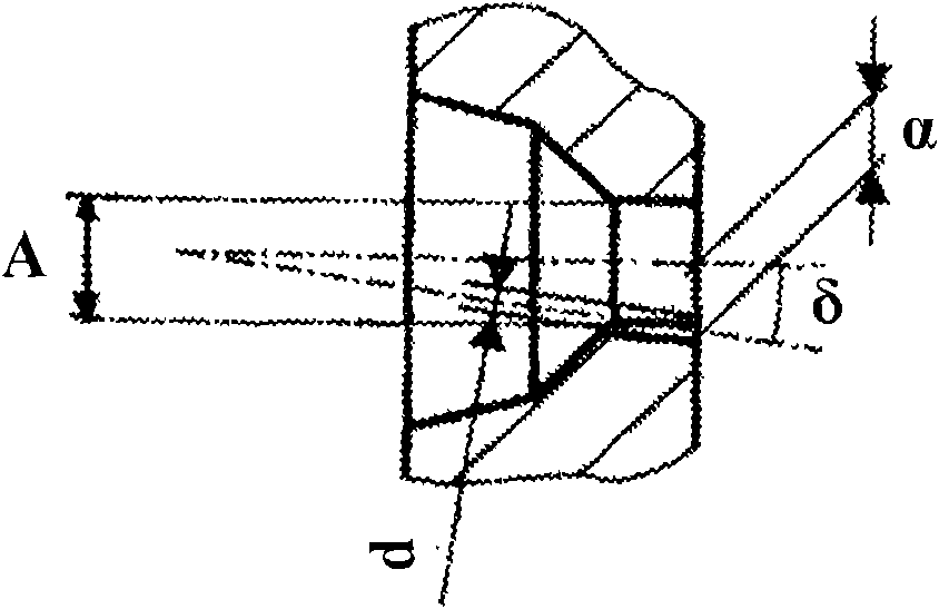
[0049] The suction chamber communicates with the high pressure chamber through a suction hole assembly with two suction holes 2 . Up to this point, the intake opening 2 , which has been congruently configured, has two frustoconical sections 8 , 9 . The opening angle α of the frustum section 8 close to the piston 4 is greater (approximately 25°) than the opening angle β of the frustum section 9 remote from the piston, which is approximately 9° in the exemplary e...


PUM


Abstract

The present invention provides a jet pump for an internal-combustion engine and an internal-combustion engine having the jet pump, in particular a jet pump for an internal-combustion engine having an absorption chamber, a high-pressure chamber, an absorption hole assembly with at least an absorption hole connecting to the absorption chamber and the high-pressure chamber, and a piston for isolating the high-pressure chamber relative to the absorption chamber, the piston has control edges for connecting the absorption chamber and the high-pressure chamber, wherein holes of the absorption hole assembly have two approximately cone shaped sections with different hole opening angles (alpha is not equal to beta), the jet pump has precontrol holes, thereby being construced in the absorption holes of the absorption hole assembly, such that in compression movement of the piston, the control edges firstly make the precontrol holes connects to the high-pressure chamber.

Description

technical field [0001] The invention relates to an injection pump for an internal combustion engine according to the preamble of claim 1 and to an internal combustion engine with such an injection pump. Background technique [0002] From the document DE 10 2005 025 601 A1 known such an injection pump for internal combustion engines according to the preamble of claim 1, the injection pump has a suction chamber (Saugraum) for supplying fuel to the internal combustion engine, which through The two suction holes (Saugbohrungen) communicate with the high-pressure chamber, and if the cam-controlled piston moves towards the high-pressure chamber during the compression movement, the piston first isolates (absperren) the high-pressure chamber from the suction chamber and continues the compression at The fuel in the high-pressure chamber is injected into the combustion chamber of the internal combustion engine. [0003] In order to achieve different pumping volumes in the constant re...

Claims


Application Information

Patent Timeline
Patent Type & Authority Applications(China)
IPC IPC(8): F02M59/26
CPCF02M59/26F02M59/44F02M59/10
Inventor L·梅尔C·施罗特
Owner MAN ENERGY SOLUTIONS SA
Why Eureka
Try Eureka