Eureka AIR delivers breakthrough ideas for toughest innovation challenges, trusted by R&D personnel around the world.

Plasma display panel and front substrate thereof

A plasma display and front substrate technology, applied in the direction of solid cathode parts, cold cathode tubes, etc., can solve the problems of low effective capacitance, decrease of PDP brightness, increase of discharge current, etc., to increase effective capacitance, improve discharge efficiency, The effect of increasing the aperture ratio

Inactive Publication Date: 2011-08-24
SICHUAN COC DISPLAY DEVICES
View PDF2 Cites 0 Cited by
  • Summary
  • Abstract
  • Description
  • Claims
  • Application Information

AI Technical Summary

Problems solved by technology

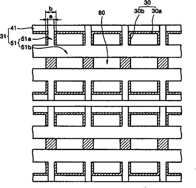
The mechanism is that if the width of the extended transparent electrode 51a is too small, the resistance of the PDP increases significantly, so the brightness of the PDP decreases, thereby reducing the luminous efficiency.
On the other hand, if the width of the extended transparent electrode 51a is too large, the width b of the first barrier rib 30b is too large, the extended transparent electrode 51a protrudes from the side of the vertical unit 30b to reduce the aperture ratio of the PDP, and due to the discharge The sharp increase of current reduces the luminous efficiency of PDP
[0009] But when figure 1 In the structure shown, there are disadvantages of large screen capacitance and low effective capacitance, so it is difficult to further improve the discharge efficiency

Method used


Image

  • Plasma display panel and front substrate thereof
  • Plasma display panel and front substrate thereof
  • Plasma display panel and front substrate thereof

Examples


Embodiment Construction

[0021] The specific implementation manners of the present invention will be described in detail below with reference to the accompanying drawings.

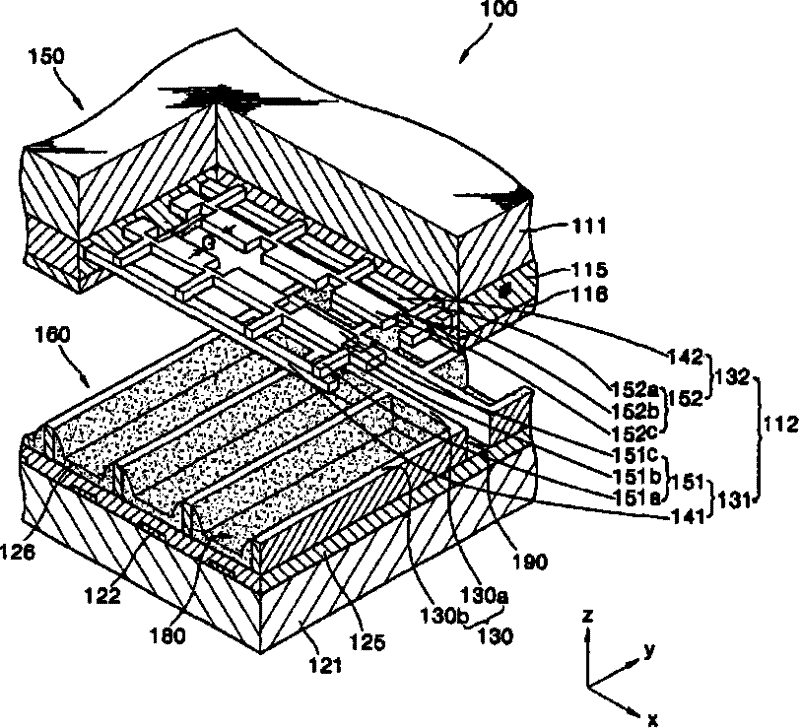
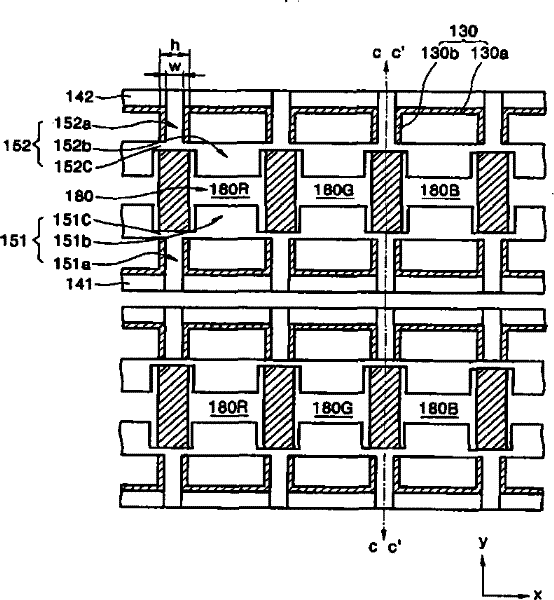
[0022] figure 2 is a partially exploded perspective sectional view of a plasma display screen according to an embodiment of the present invention, image 3 yes figure 2 The top view of the barrier rib structure and the sustain electrode structure of the shown plasma display.

[0023] Such as figure 2 As shown, the PDP 100 includes a front substrate 150 and a rear substrate 160 facing the front substrate. Pairs of sustain electrodes 112 are arranged and arranged on the lower surface of the front substrate 150 . Each pair of sustain electrodes 112 includes X electrodes 132 and Y electrodes 131 . The X electrodes 132 correspond to common electrodes, and the Y electrodes 131 correspond to scan electrodes.

[0024] The X electrodes 132 and the Y electrodes 131 respectively include transparent electrodes (generally made of ITO)...


PUM


Abstract

The invention discloses a plasma display panel and a front substrate thereof. The front substrate comprises a plurality of pairs of maintaining electrodes distributed on the lower surface of the front substrate, front medium layers covered on the maintaining electrodes and the lower surface of the front substrate, and protective layers covered on the lower surfaces of the front medium layers; each pair of the plurality of pairs of maintaining electrodes comprise public electrodes and scanning electrodes, the public electrode and the scanning electrodes all comprise bus electrodes and transparent electrodes, wherein each transparent electrode comprises a discharge transparent electrode, an extending transparent electrode which extends from the top of one of a plurality of first retaining walls on a rear substrate of the plasma display panel and is connected with each bus electrode, and a connecting transparent electrode connected with the discharge transparent electrode and the extending transparent electrode; and the bus electrodes are arranged on one of a plurality of second retaining walls on the rear substrate of the plasma display panel and a place corresponding to one of the second retaining walls.

Description

technical field [0001] The invention relates to the field of displays, more specifically to a plasma display screen and its front substrate. Background technique [0002] Plasma display (PDP) can be divided into two categories according to the driving method, namely DC PDP (DC-PDP) and AC PDP (AC-PDP), and can also be divided into two categories according to the electrode structure, namely two-electrode type PDP and three-electrode type PDP. Mainly adopt AC-PDP at present. [0003] According to the setting of the discharge electrodes, the AC-PDP can be further divided into a facing discharge type PDP and a surface discharge type PDP. For the surface discharge PDP, the two sustain electrodes are on the same substrate, and the address electrodes are provided on the other substrate. [0004] The surface discharge type AC-PDP display screen is composed of two substrates. The structure of the front substrate (the first substrate) is as follows: under the front substrate, there...

Claims


Application Information

Patent Timeline
Patent Type & Authority Patents(China)
IPC IPC(8): H01J17/49H01J17/04H01J17/16H01J17/02
Inventor 吴月广
Owner SICHUAN COC DISPLAY DEVICES
Why Eureka
Eureka Blog
Learn More