
Engine coupling analytical method

A coupling analysis and engine technology, applied in special data processing applications, instruments, electrical digital data processing, etc., can solve problems such as imperfect evaluation standards, high cost, and insufficient systematization, and achieve saving test costs, shortening development cycles, The effect of improving development efficiency

Inactive Publication Date: 2009-12-02
CHERY AUTOMOBILE CO LTD
View PDF0 Cites 14 Cited by
  • Summary
  • Abstract
  • Description
  • Claims
  • Application Information

AI Technical Summary

Problems solved by technology

[0003] At present, in the development of engines, it is rare to predict the structural strength of the whole engine. Generally, the method of trial and error is adopted, which is costly and takes a long time, causing some unnecessary waste.
There are also finite element calculations, but this method of finite element calculation is not considered systematic enough, the working conditions are not comprehensive enough, and the evaluation criteria are not perfect

Method used


Image

  • Engine coupling analytical method

Examples


Embodiment 1

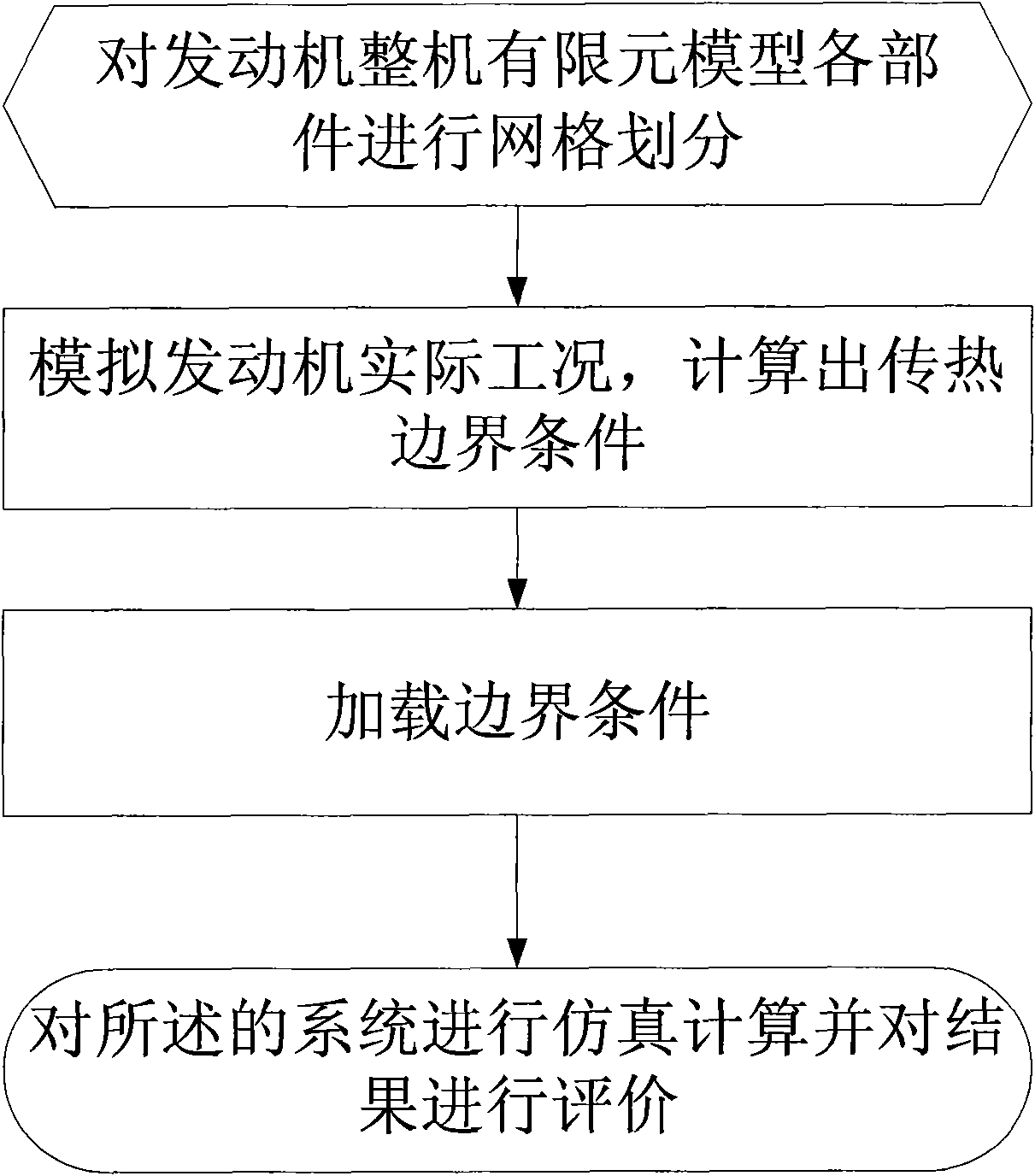
[0018] Example 1, such as figure 1 Shown: the present invention utilizes computer simulation to realize engine development, and the coupling analysis of the whole machine is mainly aimed at engine under cold state and hot state environment, several extreme working conditions are investigated its temperature, strength, deformation and fatigue performance and comprise the following steps:

[0019] Step A: Carry out mesh division for each part of the finite element model of the whole engine;

[0020] In this embodiment, meshing is performed on the components included in the analysis such as the cylinder block, cylinder head, frame, valve, valve guide rod, valve seat ring, cylinder gasket, spark plug, and cylinder head bolts. Use DS6 type unit (second-order 6-node 2D heat transfer unit), DC3D10 type unit (second-order 10-node 3D heat transfer unit), and C3D10M type unit (modified second-order 10-node 3D unit) as the basic unit of the grid, In the parts prone to stress concentrati...


PUM


Abstract

The invention fully discloses an engine coupling analytical method, which uses finite element technology to calculate a temperature field, thermal stress, mechanical stress, fatigue and the like of a complete machine of an engine and to establish a set of checking methods and procedures so as to better guide the engine product design and evaluate the reasonableness of the whole structure to improve accordingly. The method comprises the following steps of: carrying out grid partition on components of a finite element model of the complete machine of the engine; simulating an actual working condition of the engine; calculating a heat transmission boundary condition; and loading the boundary condition to carry out simulation calculation on a system and evaluate the result. The development cycle of products is greatly shortened by using the technical proposal. Various performances of the actual working condition of the engine can be simulated in a virtual environment before trial-produce of samples. The method improves the development efficiency, saves a great amount of testing cost and points out the direction for the structure design of the complete machine of the engine.

Description

technical field [0001] The invention relates to an engineering analysis method for engine research and development, in particular to using mathematical methods to establish a mathematical model at the initial stage of engine development, to simulate the actual working conditions of the engine, and to calculate the temperature field, thermal stress, mechanical stress and fatigue of various parts of the engine, etc. Data, virtual product design and simulation, guide the design of the engine block, cylinder head and cylinder gasket, and evaluate the engine performance. Background technique [0002] In the early development process of the engine, it is very important to accurately predict the rationality of its structural design, which includes temperature field, stress field calculation and fatigue calculation, etc., which can guide the engine block, cylinder head and cylinder gasket. Designing and evaluating engine performance, this method of virtual product design and simulat...

Claims


Application Information

Patent Timeline
IPC IPC(8): G06F17/50
Inventor 崔克天
Owner CHERY AUTOMOBILE CO LTD
Learn More