Q adjusting method for steady cavity/unsteady cavity of laser diode end-face pump solid laser
A technology of laser diodes and solid-state lasers, applied in lasers, laser parts, phonon exciters, etc., can solve the problems of complexity, thermal effect and insertion loss, and reducing the conversion efficiency of pump light to output laser, etc.
- Summary
- Abstract
- Description
- Claims
- Application Information
AI Technical Summary
Problems solved by technology
Method used
Image

Examples
Embodiment 1
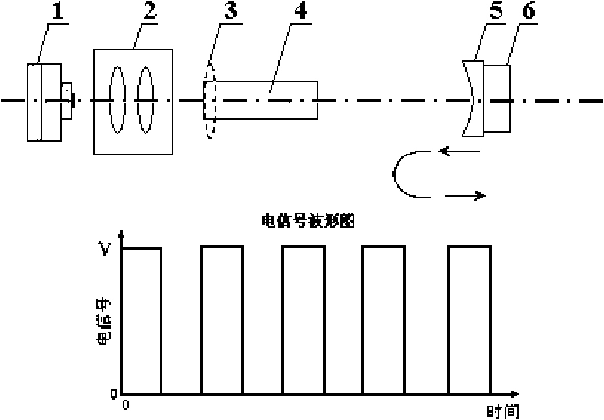
[0017] Embodiment 1: as figure 1 As shown, the laser diode end-pumped solid-state laser includes a pump source laser diode 1 , a coupling system 2 , and a laser resonator. The laser resonator includes a laser crystal 4 and an output mirror 5 . The rear end surface of the output mirror 5 is connected with the telescopic surface of the piezoelectric ceramic device 6, and the stretching and wriggling of the piezoelectric ceramic device 6 is controlled by electric signals, and the mirror surface of the output mirror 5 is perpendicular to the optical path. The output beam of the laser diode 1 is injected into the laser crystal 4 in the resonant cavity through the coupling system 2. Due to the high energy of the pump light, a thermal effect is generated inside the laser crystal 4, so that the crystal thermal lens 3 is formed in the resonant cavity. At this time, the crystal thermal lens The focal length of 3 is greater than the length of the resonator, the laser has laser output, an...
Embodiment 2
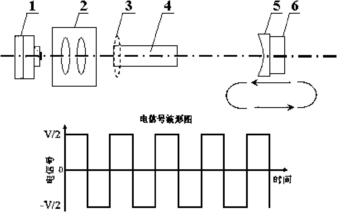
[0018] Embodiment 2: as figure 2 As shown, the system structure is the same as that of Embodiment 1, the difference is that the electrical signal applied to the piezoelectric ceramic device 6 is as follows figure 2 As shown, when a negative voltage is applied, the thickness of the piezoelectric ceramic device 6 is smaller than the initial state. At this time, the pump power is increased, and the focal length of the crystal thermal lens 3 is shortened. When the focal length is smaller than the cavity length, the resonant cavity is in an unstable state. When the resonant cavity loses a lot, there is no laser output, and the pump light causes the number of energy-level particles on the laser crystal 4 to accumulate and store energy; when a positive voltage is applied, the thickness of the piezoelectric ceramic device 6 is greater than the initial state, driving the output mirror 5 to move at On the path parallel to the optical axis, the cavity length of the resonant cavity is s...
Embodiment 3
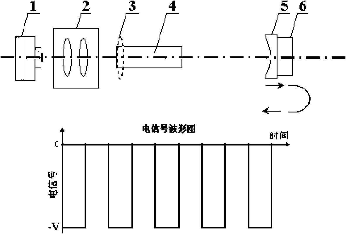
[0019] Embodiment 3: as image 3 As shown, the system structure is the same as that of Embodiment 1, the difference is that the electrical signal applied to the piezoelectric ceramic device 6 is as follows image 3 As shown, when a negative voltage is applied, the thickness of the piezoelectric ceramic device 6 is smaller than the initial state. At this time, the pump power is increased, and the focal length of the crystal thermal lens 3 is shortened. When the focal length is smaller than the cavity length, the resonant cavity is in an unstable state. When the resonant cavity loses a lot, there is no laser output, and the pumping light causes the number of energy-level particles on the laser crystal 4 to accumulate and store energy; when the voltage is zero, the thickness of the piezoelectric ceramic device 6 returns to the initial state, driving the output mirror 5 to move at On the path parallel to the optical axis, the cavity length of the resonant cavity is shortened. When...
PUM
 Abstract
Description
Claims
Application Information
 - R&D
- Intellectual Property
- Life Sciences
- Materials
- Tech Scout
- Unparalleled Data Quality
- Higher Quality Content
- 60% Fewer Hallucinations
Browse by: Latest US Patents, China's latest patents, Technical Efficacy Thesaurus, Application Domain, Technology Topic, Popular Technical Reports.
© 2025 PatSnap. All rights reserved.Legal|Privacy policy|Modern Slavery Act Transparency Statement|Sitemap|About US| Contact US: help@patsnap.com