Eureka AIR delivers breakthrough ideas for toughest innovation challenges, trusted by R&D personnel around the world.

Resonant optical gyroscope simulation method

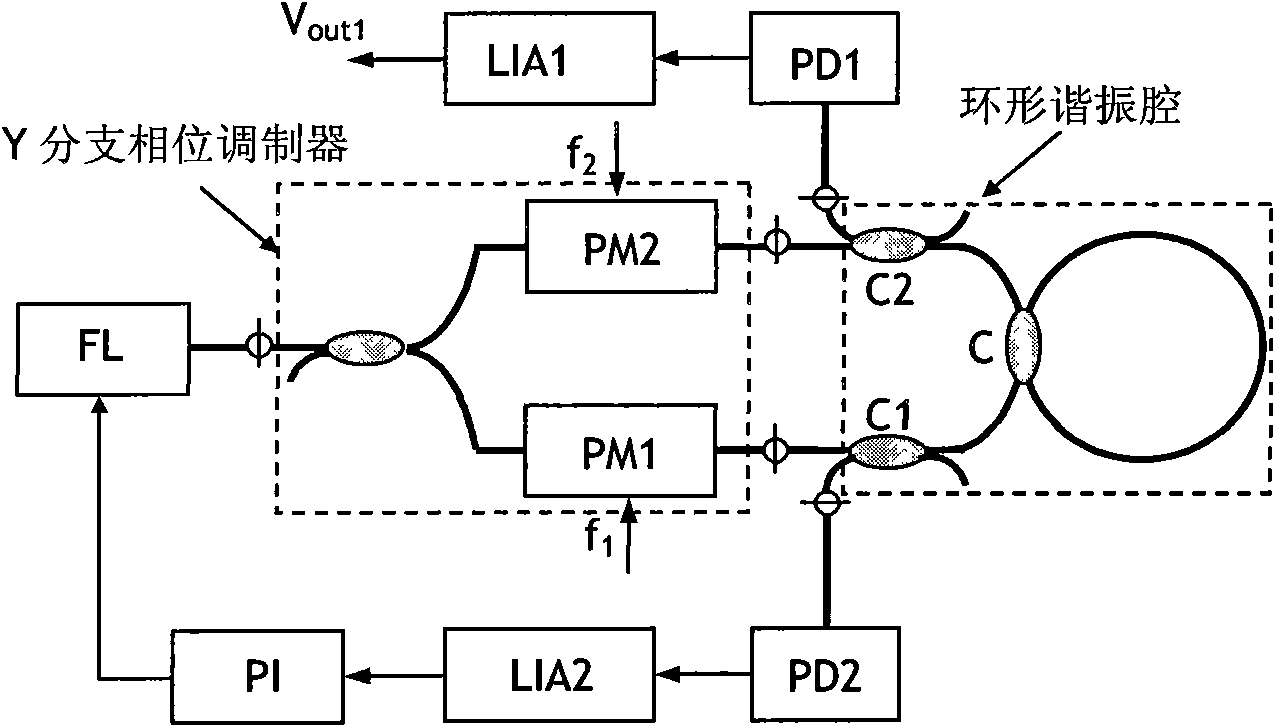
A technology of an optical gyroscope and a simulation method, applied in the field of simulation, can solve the problem that the simulation cannot match, cannot reproduce the optical noise of the resonant ring, and cannot describe the modulation and demodulation process of the resonant optical gyroscope. Process and other issues to reduce workload and enhance processing effects

Inactive Publication Date: 2009-11-25
ZHEJIANG UNIV
View PDF0 Cites 13 Cited by
  • Summary
  • Abstract
  • Description
  • Claims
  • Application Information

AI Technical Summary

Problems solved by technology

[0005] The traditional simulation method only converts the entire loop into an S-domain model similar to the phase-locked loop loop, which cannot describe the modulation and demodulation process of the resonant optical gyroscope phase modulation spectrum technology and the optical path transfer process in the resonant optical gyroscope. The generation of optical noise in the resonant ring cannot be reproduced
As a result, the simulation cannot match the actual system well

Method used


Image

  • Resonant optical gyroscope simulation method

Examples


Embodiment Construction

[0044] The resonant optical gyro simulation method includes the following steps:

[0045] 1) Initially set the global time signal required for the simulation, the global time signal controls the time alignment of the optical part and the electrical part during the simulation process, so as to maintain time synchronization throughout the simulation process;

[0046]The optical signal output by the laser module is based on timing, and the periodic superposition of the optical field in the resonant ring is also based on timing, so it is necessary to set a global time signal (global time signal) to coordinate the time synchronization of the optical module and the circuit module . The global time signal, which increases linearly from zero. Indicates the point in time the simulation is at.

[0047] 2) supply the global time signal in step 1) to each part of the data signal on the computer simulation platform, so that each part of the data signal on the computer system simulation p...


PUM


Abstract

The invention discloses a resonant optical gyroscope simulation method, comprising steps of 1) initializing a global time signal required by simulation; 2) providing the global time signal in the step 1) to various data signals on a computer simulation platform; 3) setting parameters involved in data signal process in the simulation task; 4) setting a simulation time length of simulation system; 5) starting system simulation to process signals; 6) observing and storing simulation results; 7) analyzing simulation result in the step 6) 8) changing simulation parameters for continuous simulation or simulation realized. The invention uniforms optical process and electrooptical process in resonant optical gyroscope by packaging optical and electric apparatus as modules, which greatly reduces work load of constructing system during simulation and overcomes problem that traditional method can not reproduce various optical phenomena. The optical noise is described by compute language and influence of optical noise in simulation is added, which enhances process of optical noise.

Description

technical field [0001] The invention relates to the simulation field, in particular to a resonant optical gyro simulation method. Background technique [0002] The resonant optical gyroscope is a high-precision inertial sensor device that uses the optical Sagnac effect to detect rotation. The traditional resonant optical gyro system adopts phase modulation spectrum detection technology, and the processing process is shown in Figure 1 [0003] The output light field of the laser is divided into two light fields of forward (CW: Clockwise) and counterclockwise (CCW: Counter Clockwise) through a 50% coupler, and the two light fields enter the resonant cavity through a phase modulator and a circulator respectively. After the multi-turn interference effect of the resonant cavity, they are converted into electrical signals at PD1 and PD2 respectively. Among them, after the CCW signal passes through PD2, it is synchronously demodulated by LIA2 to generate an error signal, which is...

Claims


Application Information

Patent Timeline
IPC IPC(8): G01C19/64G06F17/50
Inventor 任阳马慧莲金仲和
Owner ZHEJIANG UNIV
Why Eureka
Eureka Blog
Learn More