
Differential confocal aiming triggering type microscopic measuring method and device based on resonance girder scanning

A differential confocal and microscopic measurement technology, applied in the direction of measuring devices, optical devices, instruments, etc., can solve the problems of small range, low speed, inability to measure steps and large inclined samples, etc., to improve linearity, reduce Influence of Measurement Results, Effect of Improving Tomography Capability

Inactive Publication Date: 2011-01-12
BEIJING INSTITUTE OF TECHNOLOGYGY
View PDF3 Cites 0 Cited by
  • Summary
  • Abstract
  • Description
  • Claims
  • Application Information

AI Technical Summary

Problems solved by technology

[0020] The purpose of the present invention is to solve the problems of small range, low speed, inability to measure steps and large inclined samples in the current microscopic measurement, and propose a fast scanning and range extension based on the principle of resonant beam resonance.

Method used


Image

  • Differential confocal aiming triggering type microscopic measuring method and device based on resonance girder scanning
  • Differential confocal aiming triggering type microscopic measuring method and device based on resonance girder scanning
  • Differential confocal aiming triggering type microscopic measuring method and device based on resonance girder scanning

Examples


Embodiment

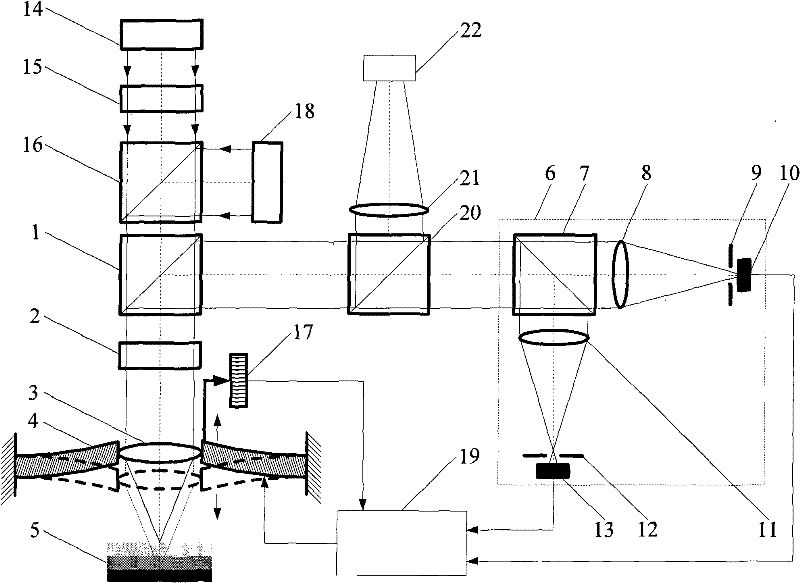
[0048] Such as image 3 As shown, a differential confocal aiming trigger microscopic measurement method based on resonant beam scanning, the measurement steps are:

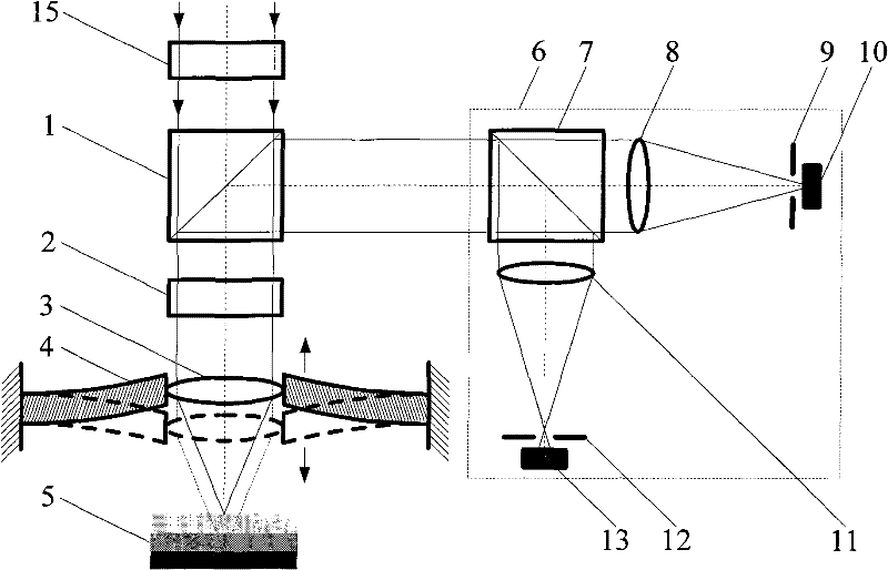
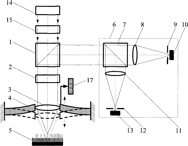
[0049] First, turn on the light source 14, emit parallel light, pass through the spectroscopic system composed of the polarizing beam splitter 1 and the 1 / 4 wave plate 2, converge on the surface of the tested sample 5 through the lens 3, and the light is reflected by the surface of the tested sample 5 Finally, it is reflected by the 1 / 4 wave plate 2 and the polarizing beam splitter 1 into the beam splitter 7 in the differential confocal collimation system 6; The object 10, the reflected light passes through the lens 11 and the pinhole 12 to the detector 13; the vibration of the resonant beam drives the objective lens 3 to perform reciprocating scanning in the direction of the optical axis. The response curve of the differential confocal aiming system 6 is as follows Figure 4 shown. By detecting the zero point ...


PUM


Abstract

The invention belongs to the optical precision measurement field, relates to a differential confocal aiming triggering type microscopic measuring method and device based on resonance girder scanning. the method utilizes the resonance of a resonance girder to drive the quick vibrating of the focusing lens in the light axis direction, the fast scan of the focusing focal point in the light axis direction is realized. a hardware zero-cross trigger circuit is used for detecting the zero of a differential confocal sensor and is matched with a precise displacement sensor to realize the rapid measurement of the displacement in the light axis direction and expand the measuring range. At the same time, the pupil filter technique is used for improving the resolution power and the sensitivity of the system. in the invention, the resonance girder way is used for realizing the axial fast scan of the differential confocal sensor, solving the problem that the traditional differential confocal displacement measurement has slow speed and small measuring range. the differential confocal type sensor detects the lighting intensity signal, with high accuracy, strong environment interference resistance,no damage for the measurand. the method can meet the requirement of high spatial resolution power, high precision and big measured range.

Description

technical field [0001] The invention belongs to the technical field of optical precision measurement, and relates to a differential confocal aiming trigger microscopic measurement method and device based on resonant beam scanning, especially suitable for surface three-dimensional micro-nano structures, micro-steps, micro-grooves, and integrated circuit lines. Detection of wide, living cells and transparent translucent materials, etc. technical background [0002] With the rapid development of semiconductor devices, MEMS devices, and MOEMS devices, microfabrication technology has entered the field of submicron and nanometer three-dimensional processing technology, and there is an urgent need for detection technology with large range, high efficiency, and high spatial resolution. At the same time, with the rapid development of disciplines such as physics, biomedicine, and materials science, such as the detection of the interior of living cells and the detection of material fau...

Claims


Application Information

Patent Timeline
Patent Type & Authority Patents(China)
IPC IPC(8): G01B11/24
Inventor 赵维谦郭俊杰邱丽荣沙定国
Owner BEIJING INSTITUTE OF TECHNOLOGYGY
Learn More