Radical self-priming fluid lubricating method for gears

A gear and lubricating oil technology, applied in the direction of gear lubrication/cooling, belt/chain/gear, transmission parts, etc., can solve the problems of insufficient oil supply for gear lubrication, complex gear structure of centrifugal lubrication method, and low oil supply efficiency, etc. Achieve the effect of thickening oil film, improving bearing capacity and high oil supply efficiency

Inactive Publication Date: 2009-11-25
章易程
View PDF0 Cites 4 Cited by
  • Summary
  • Abstract
  • Description
  • Claims
  • Application Information

AI Technical Summary

Problems solved by technology

[0002] At present, the traditional gear lubrication methods such as oil bath lubrication, splash lubrication, oil mist lubrication, grease lubrication and solid lubrication, etc., are prone to insufficient oil supply in gear lubrication under special working conditions of high speed, heavy load or vertical transmission
Although the oil injection lubrication method and the centrifugal lubrication method solve the problem of lack of oil in gear lubrication under high speed, heavy load or vertical transmission, the oil supply efficiency is low because only part of the lubricating oil enters the meshing gear pair, and additional lubrication is required. Oil injection power facilities, and the gear structure of the centrifugal lubrication method is also too complicated

Method used


Image

  • Radical self-priming fluid lubricating method for gears
  • Radical self-priming fluid lubricating method for gears

Examples


Embodiment Construction

[0009] Below in conjunction with accompanying drawing, the patent of the present invention is further described.

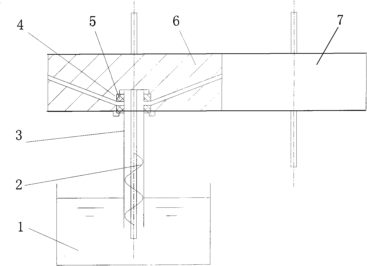
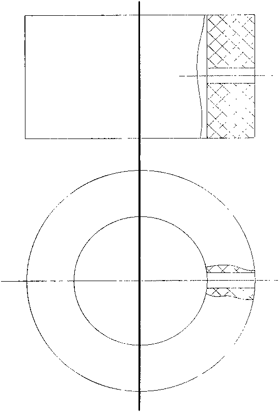
[0010] in the attached figure 1 Among them, the pump body 3 of the oil suction pump and the radial oil hole gear 6 are dynamically sealed by the sealing ring 5, and the screw 2 rotates with the gear shaft, so that the oil suction pump sucks the lubricating oil from the oil pool 1. The radial oil hole gear 6 is a gear that has an oil hole leading to each root of the gear along the radial direction. The sealing ring 5 is opened with the same number of radial holes as the radial oil hole gear 6, the two remain relatively stationary, and the radial holes of the two are kept aligned; or the sealing ring 5 is opened with a radial The oil hole remains relatively stationary with the pump body 3 of the oil suction pump, and the radial oil hole on the sealing ring 5 is aligned with the concentrated oil guide hole. On the pump body 3 of the oil suction pump, there is a con...


PUM


Abstract

The invention discloses a lubricating method for gears, comprising a oil-absorbing pump, a radial oil hole gear, a sealing ring and a concentrated oil guiding hole. The oil-absorbing pump is a screw pump or a spiral pump. The screw of the oil-absorbing pump and the gear has a same rotating shaft component. The sealing ring is arranged with radial holes with same quantity of the holes on the radial oil hole gear in a relevant static state; the radial hole are aimed; one radial oil hole on the sealing ring is relevantly static with the pump body of the oil-absorbing pump; the radial oil hole on the sealing ring is aimed at the concentrated oil guiding hole. The radial oil hole gear is the gear passing to every component along the radial direction. The concentrated oil guiding hole is arranged on the pump body of the oil-absorbing pump facing the gear meshing area. The oil-absorbing pump delivers the lubricating oil to the concentrated oil guiding hole and enters the sealing ring oil hole and the radial oil hole and enters the gear root part of the meshing position and the surface area of two gear profiles of the gears to achieve the gear lubrication. The invention can solve oil lacking phenomenon of gear pair without any additional power; the oil offering rat is high with an advantage of enhancing loading capacity.

Description

technical field [0001] The patent of the present invention relates to a lubricating method for gears, and more specifically, the patent of the present invention relates to the way of supplying lubricating oil into meshing gear pairs. Background technique [0002] At present, the traditional gear lubrication methods such as oil bath lubrication, splash lubrication, oil mist lubrication, grease lubrication and solid lubrication, etc., are prone to insufficient oil supply in gear lubrication under special working conditions of high speed, heavy load or vertical transmission . Although the oil injection lubrication method and the centrifugal lubrication method solve the problem of lack of oil in gear lubrication under high speed, heavy load or vertical transmission, the oil supply efficiency is low because only part of the lubricating oil enters the meshing gear pair, and additional lubrication is required. Oil injection power facilities, and the gear structure of the centrifug...

Claims


Application Information

Patent Timeline
Patent Type & Authority Applications(China)
IPC IPC(8): F16H57/04
CPCF16H57/0495F16H57/0428
Inventor 章易程
Owner 章易程
Why Eureka
Try Eureka