Welding fixture and welding method

A technology for welding fixtures and welding methods, applied in welding/welding/cutting items, welding equipment, manufacturing tools, etc., which can solve problems such as poor welding of welding points and inability to fully melt the self-contained solder

Active Publication Date: 2009-11-25
AU OPTRONICS (SUZHOU) CORP LTD +1
View PDF0 Cites 6 Cited by
  • Summary
  • Abstract
  • Description
  • Claims
  • Application Information

AI Technical Summary

Problems solved by technology

[0004] In view of this, the purpose of the present invention is to solve the problem of poor soldering of the solder joints caused by the insufficient melting of the self-contained solder on the second circuit board

Method used


Image

  • Welding fixture and welding method
  • Welding fixture and welding method
  • Welding fixture and welding method

Examples


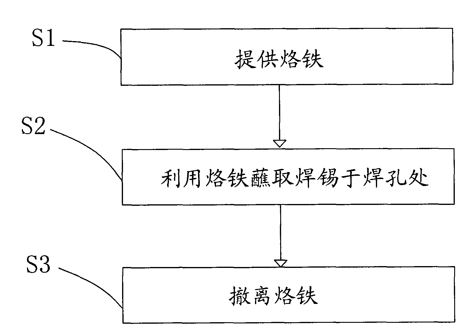
Embodiment Construction

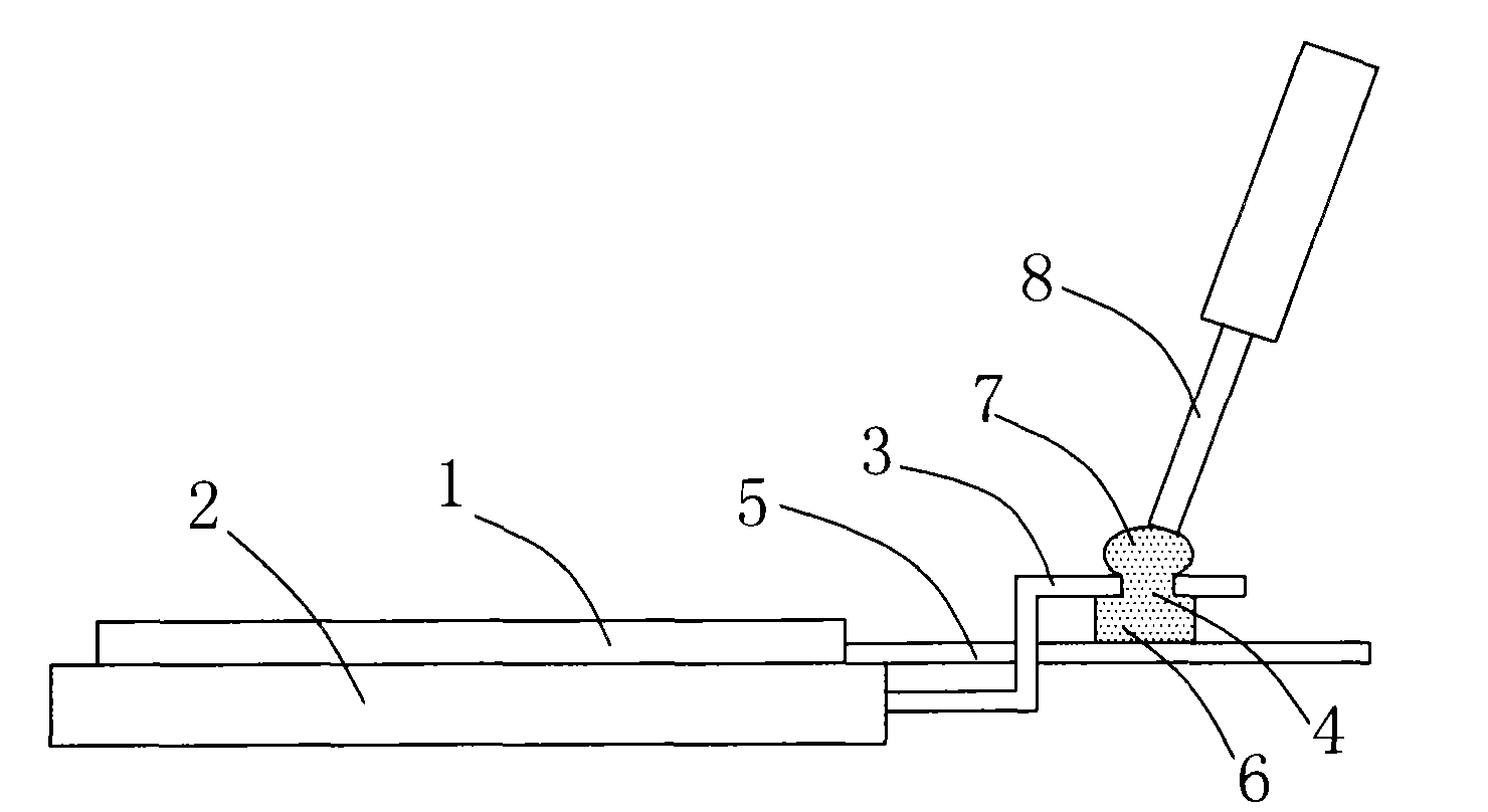
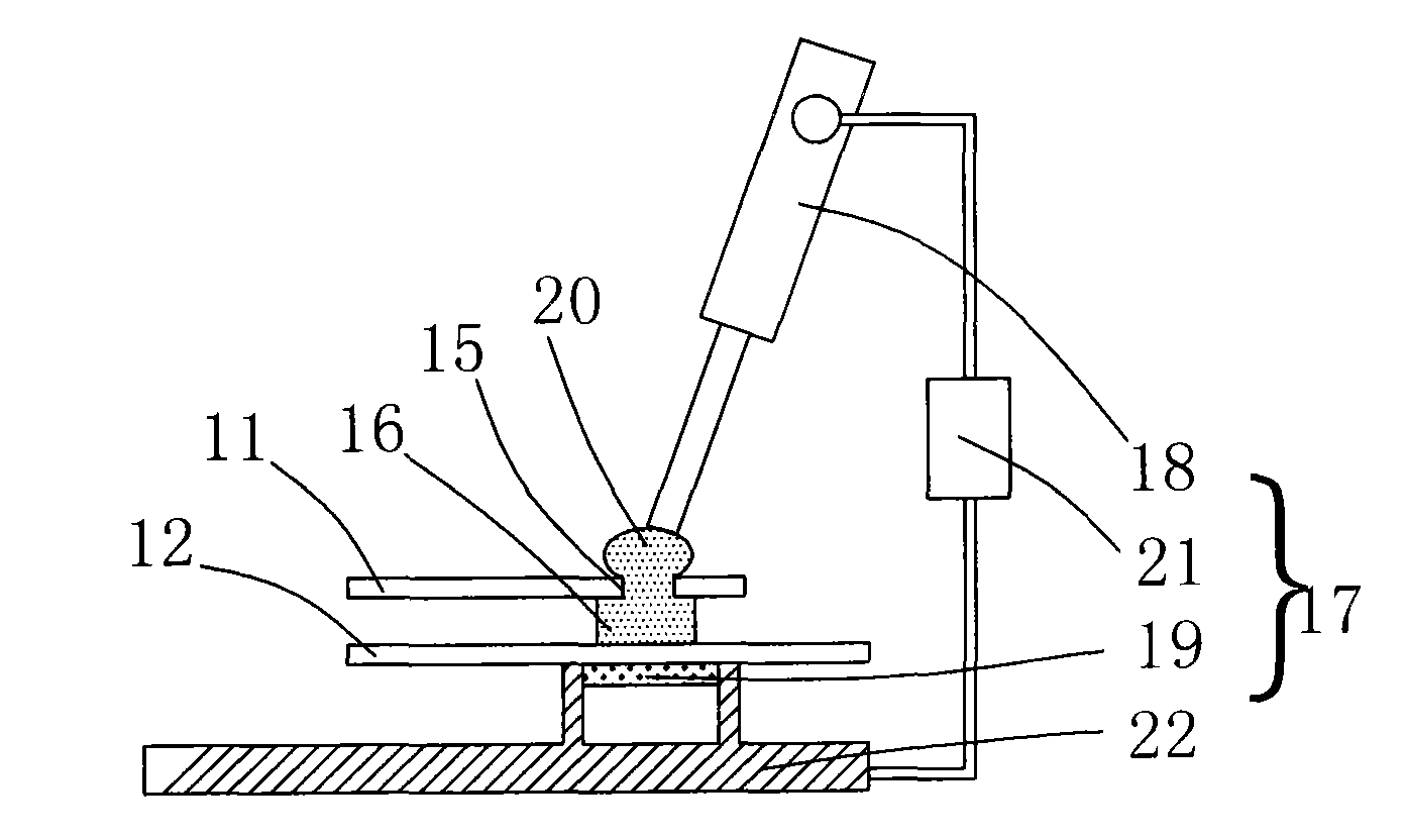
[0021] See image 3 , image 3 Shown is a schematic diagram of the combination of the welding jig and the circuit board according to the present invention. The welding jig of the present invention is used for welding the first circuit board 11 and the second circuit board 12 that are oppositely arranged. In this embodiment, the first circuit board The board 11 and the second circuit board 12 can be flexible printed circuit boards (FPC). The first circuit board 11 has solder holes 15 , and the side of the second circuit board 12 close to the first circuit board 11 has solder joints corresponding to the solder holes 15 , and the solder joints have second solder 16 .

[0022] The soldering fixture 17 includes a soldering iron 18 and a heating device 19 . The soldering iron 18 is used for dipping the first solder 20 at the solder hole 15 . The heating device 19 is disposed on a side of the second circuit board 12 away from the first circuit board 11 and corresponds to the secon...


PUM


Abstract

The invention provides a welding fixture and a welding method. The welding fixture is used for welding a first circuit board and a second circuit board which are oppositely mounted. The first circuit board is provided with welding holes; the second circuit board, near one side of the circuit board, is provide with welding points corresponding to the welding holes, and the welding points are provided with soldering tins; the welding fixture comprises an soldering iron and a heating device. The soldering iron is used for dipping the first soldering tin to the welding holes; the heating device is installed on one side of the first circuit board which is far from and corresponding to the second circuit board.

Description

technical field [0001] The present invention relates to a welding jig and a welding method, in particular to a welding jig and a welding method for a liquid crystal display module. Background technique [0002] With the advancement of science and technology, various electronic products have become an indispensable part of people's life. Among them, the display is an important component of multimedia electronic products. In a display, there are many components to be controlled and a variety of control signals. For example, the LCD panel and the backlight module need different driving signals to drive the liquid crystal molecules of the LCD panel and the light source in the backlight module. . These driving signals are generally transmitted from the driving unit to the liquid crystal display panel and the backlight module respectively through a circuit board (such as a flexible printed circuit board, FPC). [0003] At present, in the process of assembling the liquid crystal...

Claims


Application Information

Patent Timeline
Patent Type & Authority Applications(China)
IPC IPC(8): B23K3/00B23K1/00B23K101/36
Inventor 仇文操
Owner AU OPTRONICS (SUZHOU) CORP LTD
Why Eureka
Try Eureka