Flexible circuit board assembly and assembling method thereof

A flexible circuit board and assembly method technology, which is applied in the directions of printed circuit components, structural connection of printed circuits, and assembling printed circuits with electrical components, can solve the problem of poor positioning between the main flexible circuit board and the light source flexible circuit board, Problems such as release paper falling off, poor drawing and welding operation, etc.

Active Publication Date: 2015-03-11
AU OPTRONICS (XIAMEN) CORP +1
View PDF6 Cites 0 Cited by
  • Summary
  • Abstract
  • Description
  • Claims
  • Application Information

AI Technical Summary

Problems solved by technology

[0005] However, for the above-mentioned first method, since there is a gap between the positioning hole (usually a round hole) and the positioning pin of the pull-soldering jig, the main FPC and the light source FPC may be caused by relative rotation. Misalignment, resulting in poor pull welding operation
For the above second method, due to the addition of a double-sided tape, it will increase the cost
In addition, the double-sided tape attached to the light source flexible circuit board is relatively small, so it is easy to cause the release paper to fall off, resulting in poor positioning of the main flexible circuit board and the light source flexible circuit board

Method used


Image

  • Flexible circuit board assembly and assembling method thereof
  • Flexible circuit board assembly and assembling method thereof
  • Flexible circuit board assembly and assembling method thereof

Examples


Embodiment Construction

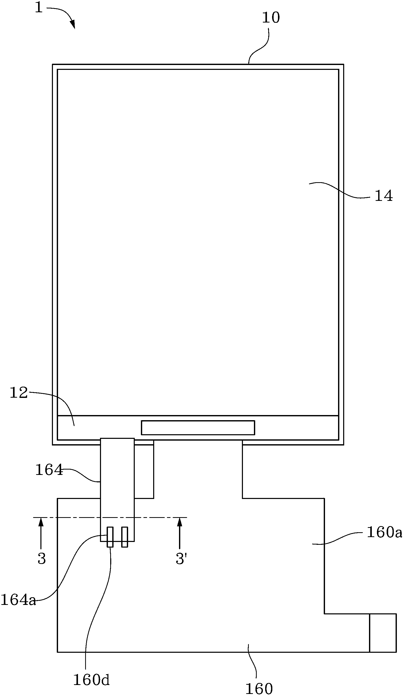
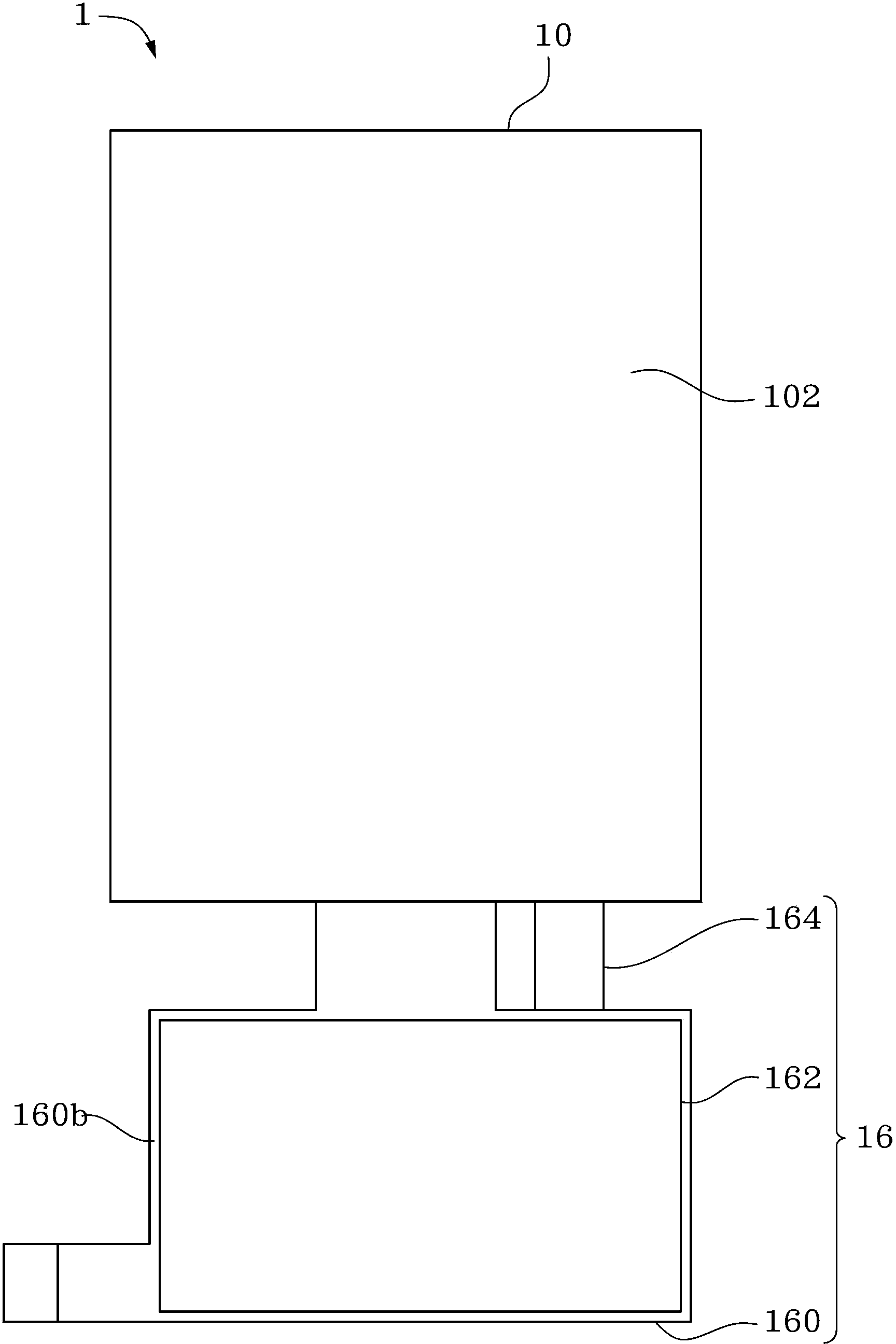
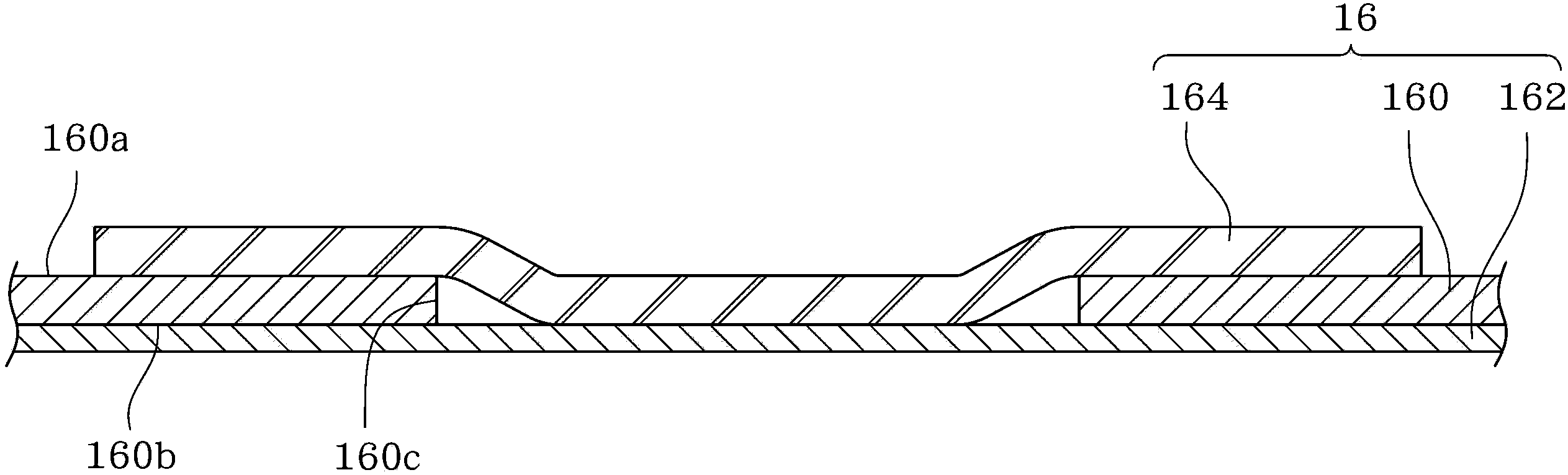
[0043] A number of embodiments of the present invention will be disclosed in the following figures. For the sake of clarity, many practical details will be described together in the following description. It should be understood, however, that these practical details should not be used to limit the invention. That is, in some embodiments of the present invention, these practical details are unnecessary. In addition, for the sake of simplifying the drawings, some commonly used structures and components will be shown in a simple and schematic manner in the drawings.

[0044] Please refer to figure 1 , figure 2 as well as image 3 . figure 1 A top view of the display 1 according to an embodiment of the present invention is shown, wherein the flexible circuit board assembly 16 has not yet been assembled to the backplane 10 . figure 2 draw figure 1 Bottom view of display 1 in . image 3 draw figure 1 The schematic cross-sectional view of the flexible printed circuit board...


PUM


Abstract

The invention provides a flexible circuit board assembly and an assembling method thereof. The flexible circuit board assembly comprises a first flexible circuit board, an adhesion piece and a second flexible circuit board. The first flexible circuit board is provided with a first surface, a second surface and a through hole for communicating the first surface with the second surface. The adhesion piece is arranged on the second surface and covers the through hole. The second flexible circuit board is arranged on the first surface. Part of the second flexible circuit board is glued with the adhesion piece through the through hole. Due to the adoption of the flexible circuit board assembly, the adhesion piece glued on the second surface of the first flexible circuit board is utilized to be simultaneously glued with the second flexible circuit board on the first surface of the first flexible circuit board. An area of the first flexible circuit board, which is overlapped relative to second flexible circuit board, is partially excavated to form the through hole, so that the second flexible circuit board on the first surface can be mutually glued with the adhesion piece on the second surface through the through hole. Therefore, the aim of mutual location of the first soft flexible circuit board and the second soft flexible circuit board is achieved.

Description

technical field [0001] The invention relates to a flexible circuit board combination, in particular to a flexible circuit board combination in a display. Background technique [0002] In recent years, due to the rapid development of the electronics and information industries, their related products have become increasingly sophisticated. As far as the current personal computer field is concerned, in addition to seeking higher-speed computing units with stronger computing capabilities and a variety of peripheral devices to meet the needs of users, thin and light portable computers are also the development of the industry. Important area. Taking liquid crystal display as an example, it has the advantages of high image quality, small size, light weight, low voltage drive, low power consumption and wide application range, so it is widely used in portable TVs, mobile phones, video recorders, etc. , notebook computers, desktop monitors and other consumer electronics products hav...

Claims


Application Information

Patent Timeline
Patent Type & Authority Patents(China)
IPC IPC(8): H05K1/14H05K3/36
Inventor 颜华生
Owner AU OPTRONICS (XIAMEN) CORP
Why Eureka
Try Eureka