
Method for modeling seamless acoustic transmission channel of periodic drill rod

A technology of transmission channel and modeling method, which is applied in the modeling field of seamless acoustic wave transmission channel, can solve the problems of unsatisfactory transmission effect and poor versatility, and achieve the effect of strong applicability, good versatility and reliable transmission results

Inactive Publication Date: 2009-11-18
XI'AN PETROLEUM UNIVERSITY
View PDF9 Cites 10 Cited by
  • Summary
  • Abstract
  • Description
  • Claims
  • Application Information

AI Technical Summary

Problems solved by technology

[0013] The present invention provides a modeling method for the seamless acoustic wave transmission channel of periodic drill pipes, so as to overcome the problem of unsatisfactory transmission effect caused by the poor versatility of the properties of the acoustic wave transmission channel in the prior art

Method used


Image

  • Method for modeling seamless acoustic transmission channel of periodic drill rod
  • Method for modeling seamless acoustic transmission channel of periodic drill rod
  • Method for modeling seamless acoustic transmission channel of periodic drill rod

Examples


Embodiment 1

[0125] Two, embodiment 1: drill pipe

[0126] The frequency response parameters of multiple uniform oil pipes are already known. For example, the parameters of five uniform oil pipes are as follows:

[0127] Table 1. Drill string parameters.

[0128]

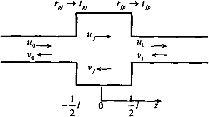
[0129] Douglas S.Drumheller and Thomas G.Barnes respectively used finite difference and characteristic equations to give the frequency response of sound waves propagating in oil pipes, and found that when sound waves propagate in periodic oil pipes, they have frequency passband and forbidden band characteristics, and their frequency response Curves are similar to comb filters, see Figure 7 right picture. Figure 7 The figure on the left shows the transmission characteristics calculated with the seamless acoustic wave model proposed by the present invention. It can be seen that under the same conditions, the two models have obtained the same results, but the present invention has more advantages than it. The present inven...

Embodiment 2

[0132] 3. Embodiment 2: oil pipe

[0133] The modeling method of the present invention will be further described below through the calculation of the sound path characteristics of the drill pipe under different drilling tool combinations.

[0134] The tubing has two structures:

[0135] tubing type

Inner diameter mm

Outer diameter mm

cross-sectional area

length m

[0136] m 2

big tubing

151.52

178

0.0274

9

small tubing

151.52

178

0.0274

1.55

[0137] There are also two types of couplings, one of which is a joint that exists in the middle of a small tubing:

[0138]

Coupling type

Inner diameter mm

Outer diameter mm

cross-sectional area

m 2

length m

Coupling

151.52

203

0.0573

0.13

middle of small tubing

connector

151.52

...


PUM


Abstract

The invention relates to the technical field of acoustic telemetry of bidirectional data between the well bottom and the ground during the drilling, in particular to a method for modeling a seamless acoustic transmission channel of a periodic drill rod. The method aims to solve the problem of nonideal transmission effect caused by poor universality of the characteristics of acoustic transmission channels existing in the prior art. To solve the problem existing in the prior art, the invention provides the method for modeling the seamless acoustic transmission channel of the periodic drill rod. Compared with the prior art, the method has the advantages that: a drilling column string acoustic channel propagation model which is seamless and can be freely assembled is developed, is closely combined with the actual field using condition, and has strong applicability and reliable transmission results; the model can perform research and analysis on acoustic wave propagation characteristics of a drilling column string of any drilling tool assembly; and the method establishes acoustic transmission theories for the drilling columns of different drilling tool assemblies, and lays the foundation for developing related instruments in the future.

Description

Technical field: [0001] The invention relates to the technical field of acoustic wave remote transmission of two-way data between the bottom of a well and the ground during drilling, in particular to a modeling method for a seamless acoustic wave transmission channel of a periodic drill pipe. Background technique: [0002] The two-way data transmission technology between the bottom of the well and the ground plays an increasingly important role in modern drilling technology. At present, the commercially used mud pulse generators in the drilling market have the disadvantages of low transmission rate, serious dependence on drilling fluid, and high cost of use and maintenance. Therefore, in recent years, foreign countries have carried out research in the field of acoustic wave remote transmission technology to replace mud pulse generators. [0003] Acoustic remote transmission technology refers to the method in which acoustic wave transducers generate longitudinal elastic wave...

Claims


Application Information

Patent Timeline
Patent Type & Authority Applications(China)
IPC IPC(8): H04B11/00E21B47/14
Inventor 周静傅鑫生张峰刘惠恩雷诚傅杰
Owner XI'AN PETROLEUM UNIVERSITY
Learn More