
Drop hammer impact testing machine

A drop hammer impact test and column technology, which is applied to measuring devices, instruments, scientific instruments, etc., can solve the problems of high labor intensity, time-consuming, low efficiency, etc., and achieve the goal of improving work efficiency, saving test time, and reducing labor intensity Effect

Inactive Publication Date: 2009-11-18
武汉凯盟机电工程有限公司
View PDF0 Cites 29 Cited by
  • Summary
  • Abstract
  • Description
  • Claims
  • Application Information

AI Technical Summary

Problems solved by technology

[0002] The existing drop hammer impact testing machine is fully manual operation. After each time the hammer head is manually hung on the hook, the hook is pulled up to the specified height, and then the hammer head is released to impact the sample through the weight of the hammer head. , after completing one pass, the rail rolls over or slips off the support
Then lift the rail to the support, repeatedly install the hammer on the hook, pull it up again, and then release the hammer to impact the sample. Each impact requires manual operation, so the operation is complicated and time-consuming. The rail is heavy and the operating site is limited. Small, very inconvenient, labor-intensive, usually requires 10-15 minutes for each impact, and each sample drop weight test usually needs to complete two impacts, for samples such as rails, each time The type test requires continuous testing of 25 samples, and the weld drop hammer impact test requires at least 25 consecutive completions, that is, 50 impacts. If the traditional testing machine is used, it will take a lot of time, the efficiency is very low, and the labor intensity of the workers is high.

Method used


Image

  • Drop hammer impact testing machine
  • Drop hammer impact testing machine
  • Drop hammer impact testing machine

Examples


Embodiment Construction

[0024] The present invention will be further described in detail below in conjunction with the description of the drawings and the specific embodiments:

[0025] A drop-weight impact testing machine, including the following components:

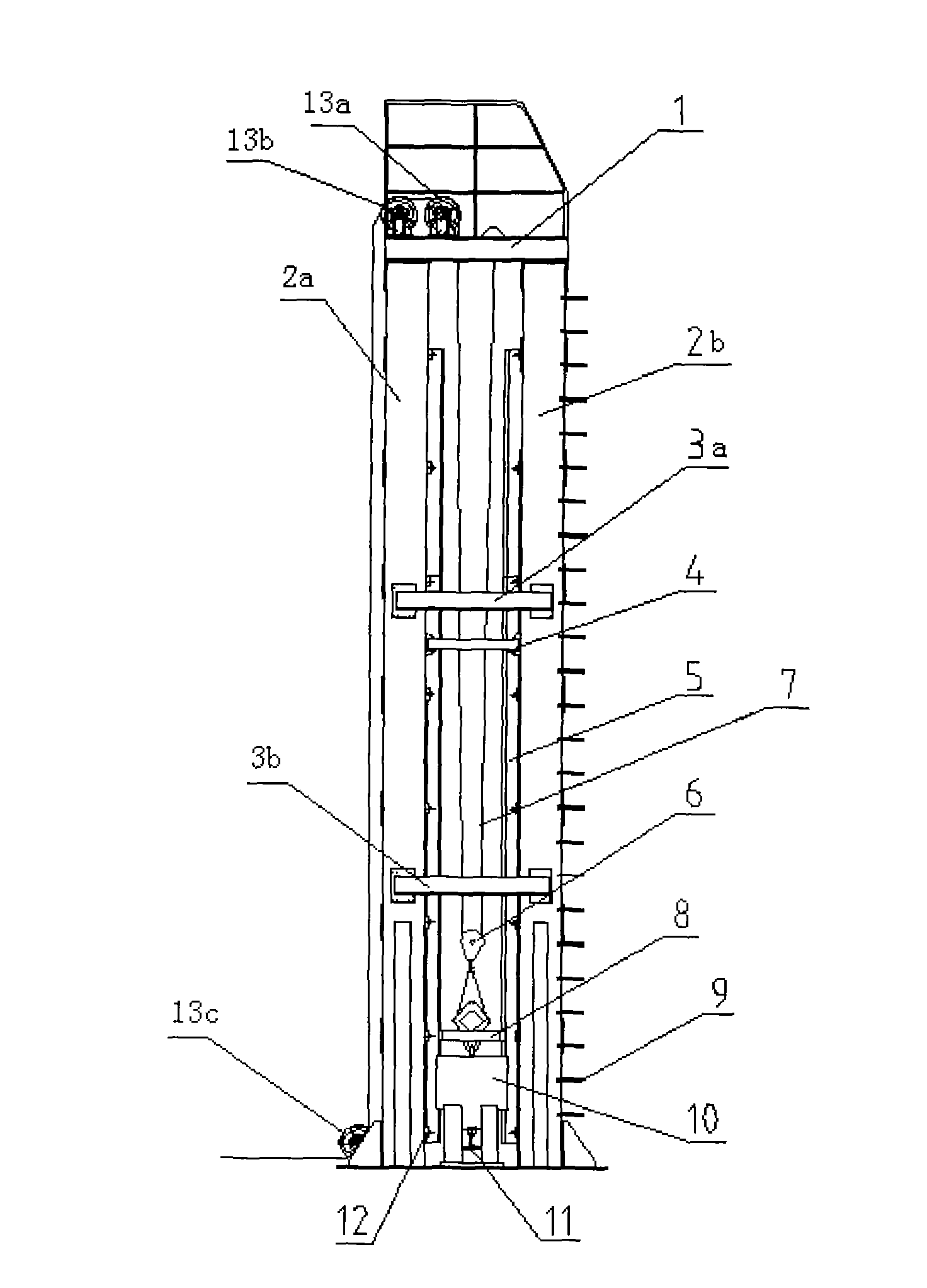
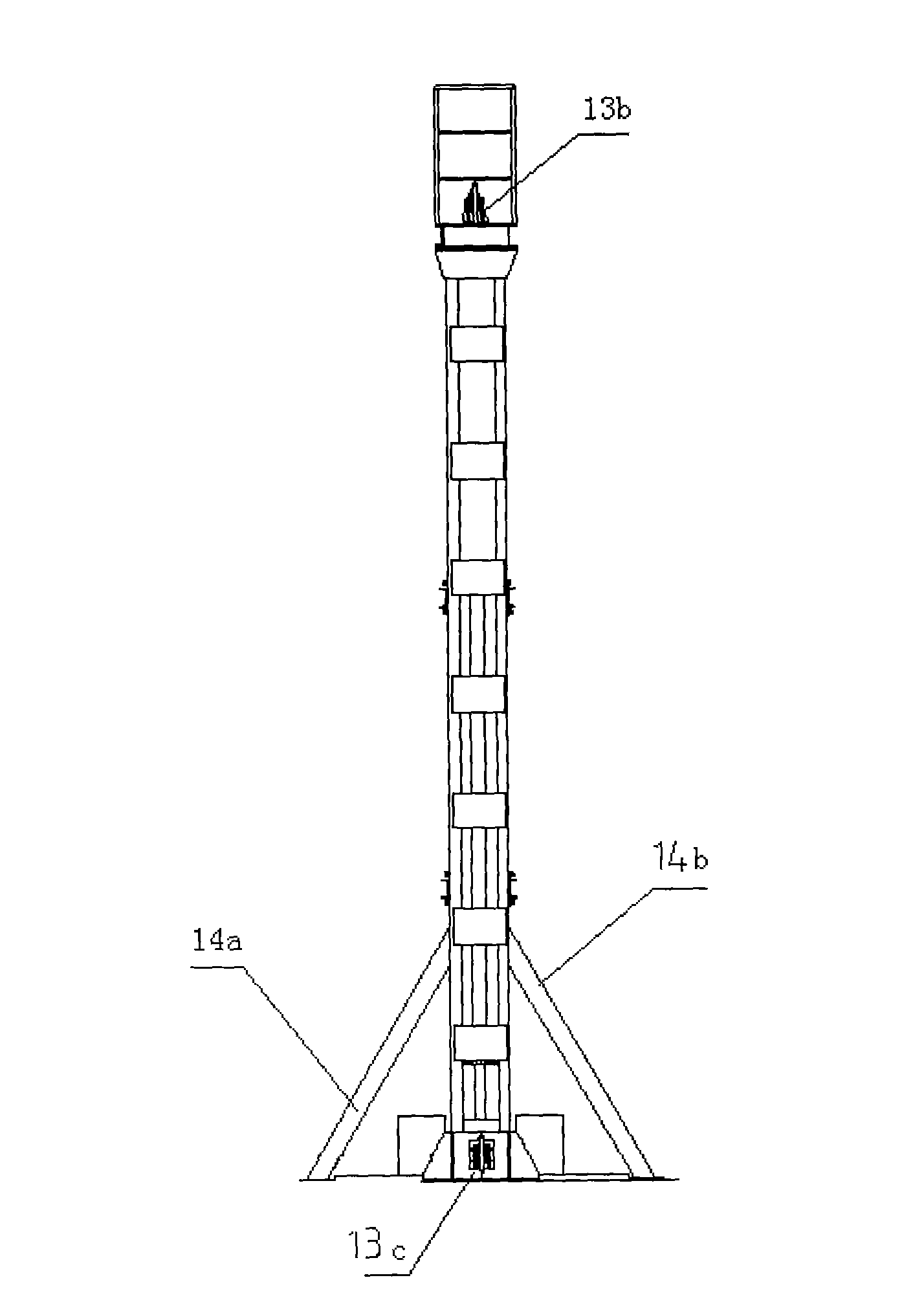
[0026] Cross beam 1, first column 2a, second column 2b, first cross brace 3a, second cross brace 3b, iron stop 4, steel rail 5, hook (with insurance card) 6, wire rope 7, grapple device 8, iron Ladder 9, impact hammer 10, rail clamping device 11, pressing plate 12, first pulley 13a, second pulley 13b, third pulley 13c, first support 14a, second support 14b.

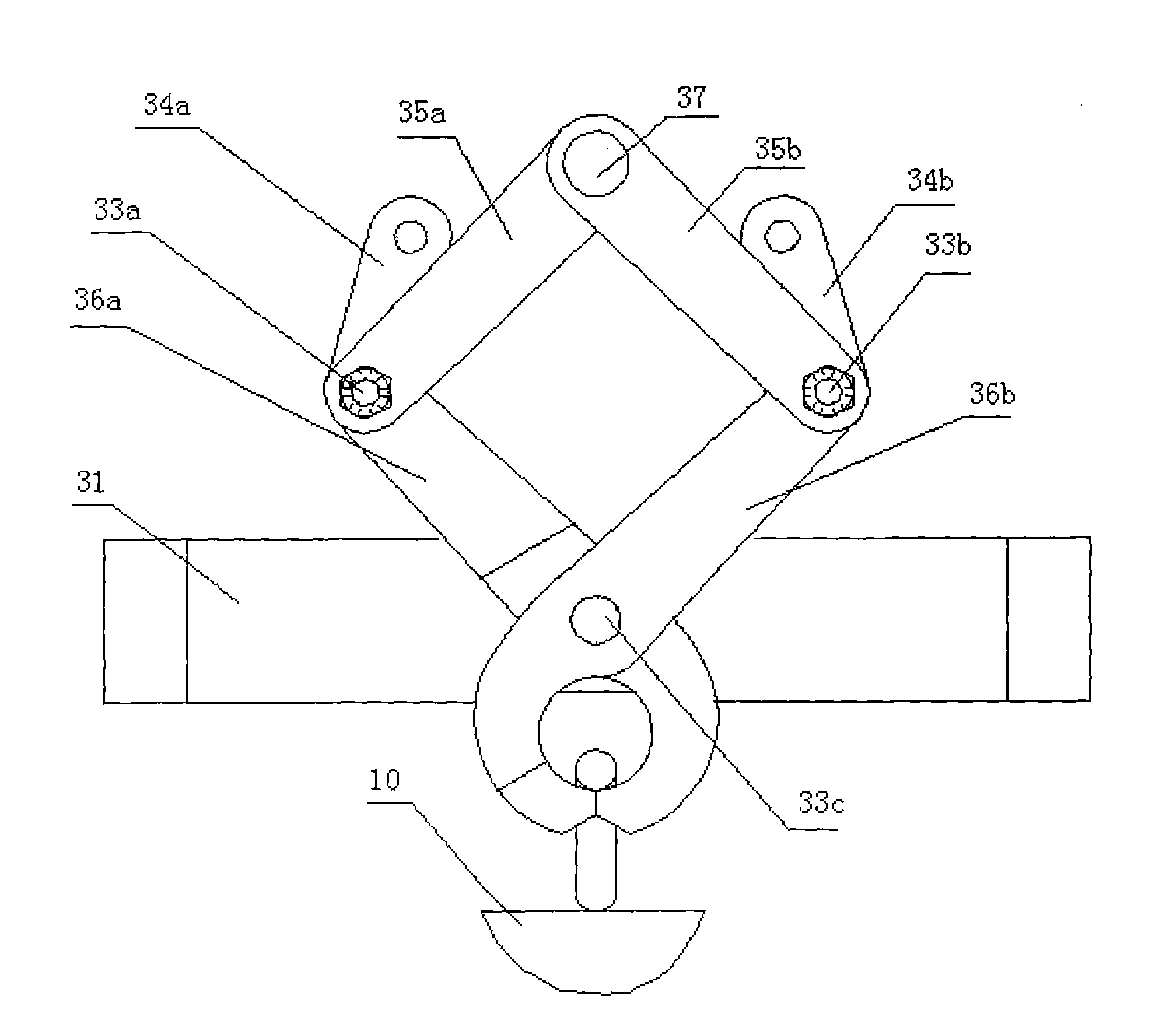
[0027] Among them, the grappling hook device 8 includes:

[0028] Guide frame 31, first shaft 33a, second shaft 33b, third shaft 33c, first hanging plate 34a, second hanging plate 34b, first link 35a, second link 35b, first clamp arm 36a, first The second clamp arm 36b, the block shaft 37.

[0029] The rail clamping device 11 includes:

[0030] The anvil 38, the first stopper 39a, and the sec...


PUM


Abstract

The invention discloses a drop hammer impact testing machine, which comprises an iron block, a drop hanger, a wire cable, a grapnel device and a rail holding device. The invention is characterized in that a beam, an upright post, a cross arm and a support are fixed to form a frame of the impact testing machine via screw bolts; a pulley is mounted on the beam and below the upright post; one end of the wire cable is arranged on the beam, and the other end thereof is connected with a power unit through the drop hanger and the pulley; the drop hanger is provided with a drop hanger device for catching and releasing an impact hammer; the rail holding device is fixed in the middle position below the upright post. By using the invention, automatically catching the hammer and automatically decoupling can be realized while the rail cannot change position to finish repeated impact tests, thus saving testing times, reducing labor strength and improving work efficiency greatly.

Description

Technical field [0001] The invention relates to a test equipment, and more specifically to a drop hammer impact tester. It is mainly used to detect the drop hammer impact test of rail welds. Background technique [0002] The existing drop hammer impact testing machine is fully manually operated. Each time the hammer is manually hung on the hook, the hook is pulled up to a specified height, and then the hammer is released, and the sample is impacted by the weight of the hammer. , After finishing once, the rail rolls over or slips off the support. Then lift the rail to support, repeatedly install the hammer head on the hook, pull it up, and then release the hammer head to impact the sample. Each impact requires manual operation, so the operation is complicated and time-consuming, the rail is heavy, and the operating site It is small, very inconvenient, and labor-intensive. It usually takes 10-15 minutes for each impact to operate. The drop weight test of each sample usually require...

Claims


Application Information

Patent Timeline
Patent Type & Authority Applications(China)
IPC IPC(8): G01N3/303
Inventor 谢鹏史珠丽徐元生
Owner 武汉凯盟机电工程有限公司
Learn More