
Phase-change temperature control device integrating heat pipe and foam metal core body

A metal foam and integrated heat pipe technology, applied in the direction of electric solid devices, semiconductor devices, indirect heat exchangers, etc., can solve the temperature gradient and concentrated thermal stress affecting the structural reliability of the phase change temperature control device, and increase the phase change temperature control device Quality and volume, weakening the thermal conductivity of the phase change temperature control device and other issues, to achieve the effect of improving the effective utilization rate, high effective utilization rate, and improving thermal conductivity

Inactive Publication Date: 2009-11-11
BEIHANG UNIV
View PDF0 Cites 38 Cited by
  • Summary
  • Abstract
  • Description
  • Claims
  • Application Information

AI Technical Summary

Problems solved by technology

[0006] However, the thermal conductivity of the phase change materials commonly used in electronic equipment temperature control is mostly low, so that the phase change materials in the phase change temperature control device cannot all participate in heat storage / discharge, thereby reducing the effective utilization rate of the phase change material and increasing the temperature. The quality and volume of the phase change temperature control device are reduced; in addition, the volume change during the phase change makes the phase change material inevitably have holes, and the existence of holes not only brings a large local thermal resistance and weakens the thermal conductivity of the phase change temperature control device , and will produce a large temperature gradient and concentrated thermal stress that will affect the structural reliability of the phase change temperature control device, which may lead to failure or even direct damage to the phase change temperature control device

Method used


Image

  • Phase-change temperature control device integrating heat pipe and foam metal core body
  • Phase-change temperature control device integrating heat pipe and foam metal core body
  • Phase-change temperature control device integrating heat pipe and foam metal core body

Examples


Embodiment Construction

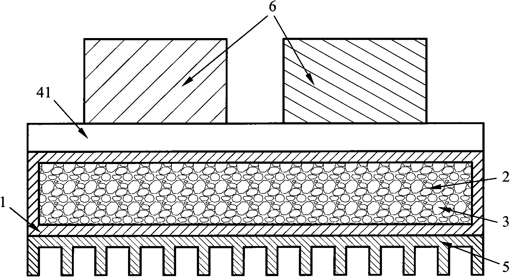
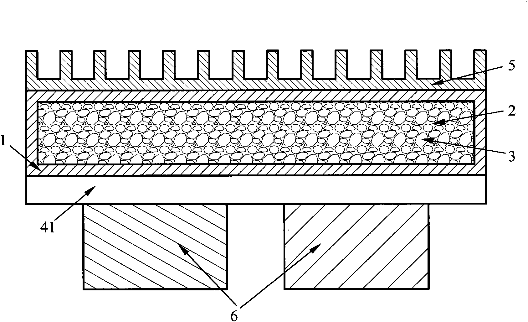
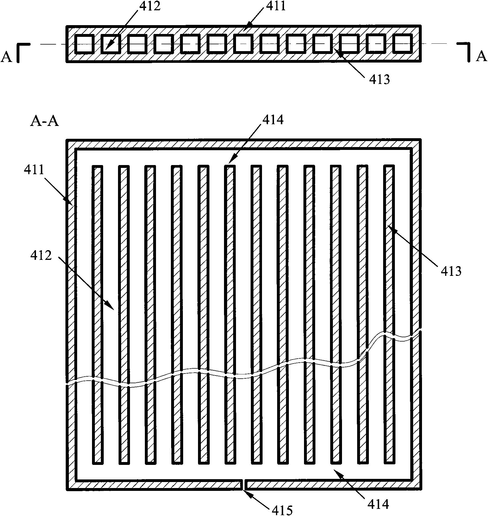
[0027] In order to further explain the technical means and effects adopted by the present invention to achieve the intended purpose of the invention, the specific implementation of the phase-change temperature control device of the integrated heat pipe and metal foam core according to the present invention will be described below in conjunction with the accompanying drawings and preferred embodiments. The method is described in detail as follows, but the examples are only for reference and illustration, and are not intended to limit the scope of application of the present invention.

[0028] Figure 1 is a cross-sectional view of a phase-change temperature control device integrating a flat heat pipe and a metal foam core. There are two types of relative positions between the phase-change temperature control device and electronic equipment, Figure 1a It shows that the electronic equipment is placed on the phase-change temperature control device (hereinafter referred to as positiv...


PUM


Abstract

The invention relates to a temperature control system of electronic equipment, which adopts phase-change materials and integrates a heat pipe and a foam metal core body. The temperature control system comprises a container, at least one heat pipe and a radiating fin, wherein the container is filled with the foam metal core body and the phase-change materials, and the at least one heat pipe can be a flat-plate type heat pipe or at least one axial non-conventional type heat pipe or at least one axial rectangle heat pipe arranged in the phase-change material container. The phase-change temperature control device integrating the heat pipe and the foam metal core body has better heat conducting property, higher effective utilization rate of the phase-change materials and more uniform temperature distribution and solves the problem that partial high temperature and concentrated heat stress generated by cavities intensively distributed in the prior phase-change temperature control device affect the reliability of the phase-change material container, thereby more effectively controlling the temperature of the electronic equipment or an electronic element.

Description

【Technical field】 [0001] The invention relates to a temperature control system for electronic equipment, in particular to a temperature control system for electronic equipment that adopts phase change materials and integrates heat pipes and metal foam cores. 【Background technique】 [0002] With the rapid development of electronic technology, electronic components are increasingly miniaturized, but power consumption is getting higher and higher, which makes the heat flux of electronic equipment increase sharply, which will cause the temperature of electronic devices to be too high when they work. The failure rate of electronic components increases exponentially with the increase of temperature. Overheating damage has become the main failure form of electronic equipment. According to statistics, 55% of electronic equipment failures are caused by excessive temperature. Therefore, effective monitoring of electronic equipment Temperature control becomes a key technology to improv...

Claims


Application Information

Patent Timeline
IPC IPC(8): H05K7/20H01L23/427F28D15/02
CPCH01L2924/0002
Inventor 徐伟强袁修干李贞
Owner BEIHANG UNIV
Learn More