Optical communication system, optical communication device and optical communication method

An optical communication system and communication device technology, applied in the field of optical network communication, can solve the problems of rising operation and maintenance costs, shortening transmission distance, etc., and achieve the effects of saving light sources and flexible wavelength allocation

Inactive Publication Date: 2009-11-11
HUAWEI TECH CO LTD
View PDF0 Cites 16 Cited by
  • Summary
  • Abstract
  • Description
  • Claims
  • Application Information

AI Technical Summary

Problems solved by technology

[0002] The traditional broadband access network based on copper wires is facing large-scale copper cable replacement and renewal due to the aging of the copper wire infrastructure, and the operation and maintenance costs are increasing year by year; on the other hand, the bandwidth requirements of users are increasing, based on Copper broadband access technologies, such as ADSL, VDSL, VDSL2, VDSL 2+, etc., can provide bandwidth that is inversely proportional to its transmission distance, that is, the larger the bandwidth, the shorter the effective transmission distance; on the other hand, Although the wireless broadband access network, such as WiMAX, is slightly inferior to the wired access network in terms of bandwidth, it relies on its natural, seamless penetration, and low single-user network construction costs and operation and maintenance costs. , posing a huge threat to the wired broadband access network with increasingly heavy O&M burden

Method used


Image

  • Optical communication system, optical communication device and optical communication method
  • Optical communication system, optical communication device and optical communication method
  • Optical communication system, optical communication device and optical communication method

Examples


Embodiment Construction

[0016] In order to make the object, technical solution and advantages of the present invention clearer, the embodiments of the present invention will be further described in detail below in conjunction with the accompanying drawings.

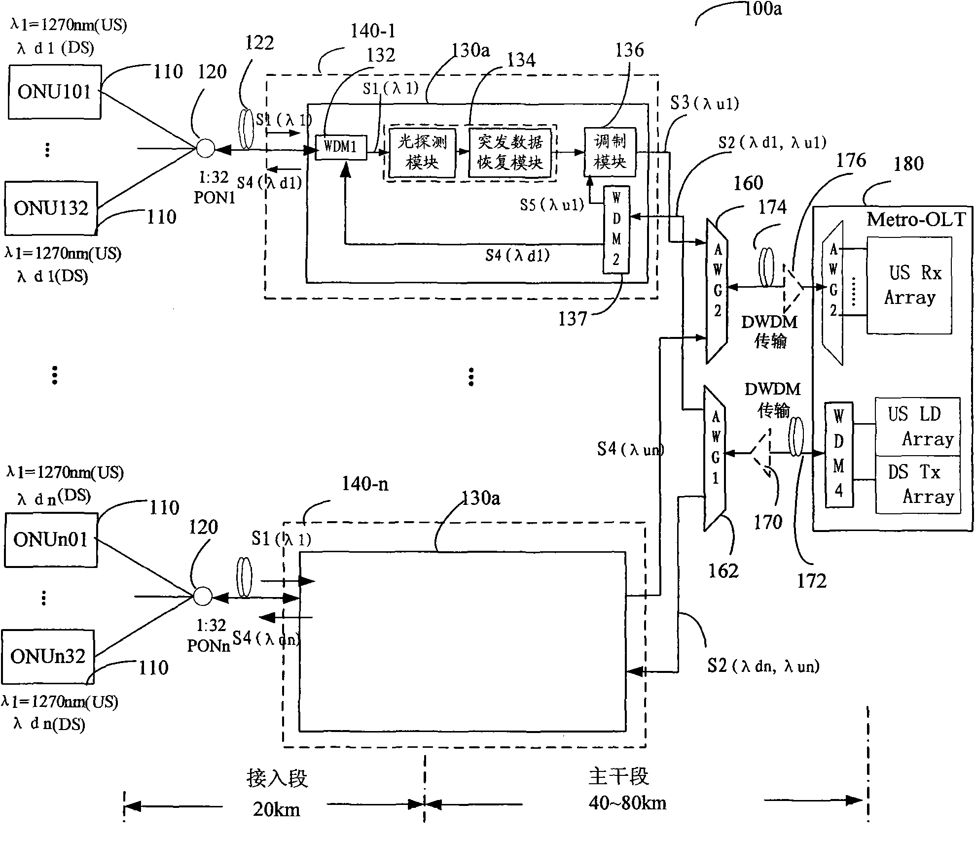
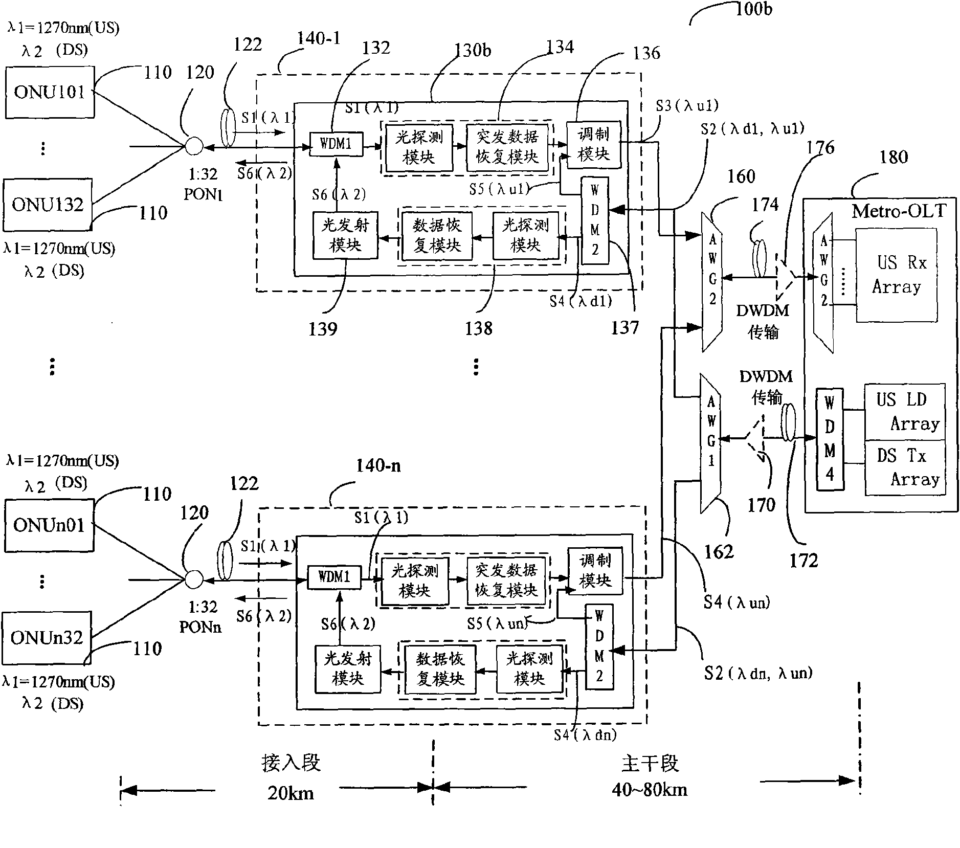
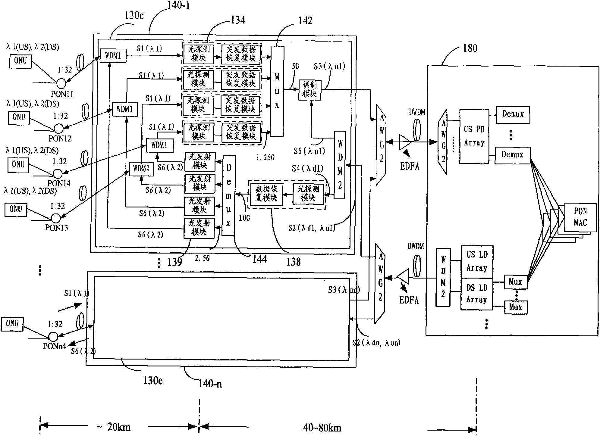
[0017] Figure 1A , Figure 1B with Figure 1C It is a schematic diagram of a communication system provided according to an embodiment of the present invention. Such as Figure 1A As shown, the communication system 100 a includes a terminal node 110 and local nodes 140 - 1 , 140 - 2 . . . 140 -n and a central node 180 . The terminal node 110 is a device located at the terminal user's premise, including an optical network terminal (Optical Network Terminal, ONT) and an optical network unit (Optical Network Unit, ONU). There are also other networks such as Ethernet. If there is no special description, they will be represented by ONU below; local nodes 140-1, 140-2...140-n are devices covering local areas. Any one of the local computer room, loc...


PUM


Abstract

The embodiment of the invention provides an optical communication system, an optical communication device and an optical communication method, wherein the optical communication system comprises at least one relay device, one end of the relay device is coupled to at least one terminal node, while the other end is coupled to a central node so as to realize the intercommunication between the terminal node and the central node; the relay device is used for receiving a first optical signal from the terminal node and a second optical signal from the central node; and after the relay device restores a data electrical signal from the first optical signal, the data electrical signal is modulated onto at least a part of the optical signal of the second optical signal, and a third optical signal obtained by modulating is sent to the central node. By adopting the scheme of the embodiment of the invention, the relay device does not need an ascending light source so as to save the light source and ensure that the wavelength allocation is more flexible.

Description

technical field [0001] The invention relates to the field of optical network communication, in particular to an optical communication system, device and method. Background technique [0002] The traditional broadband access network based on copper wires is facing large-scale copper cable replacement and renewal due to the aging of the copper wire infrastructure, and the operation and maintenance costs are increasing year by year; on the other hand, the bandwidth requirements of users are increasing, based on Copper broadband access technologies, such as ADSL, VDSL, VDSL2, VDSL 2+, etc., can provide bandwidth that is inversely proportional to its transmission distance, that is, the larger the bandwidth, the shorter the effective transmission distance; on the other hand, Although the wireless broadband access network, such as WiMAX, is slightly inferior to the wired access network in terms of bandwidth, it relies on its natural, seamless penetration, and low single-user networ...

Claims


Application Information

Patent Timeline
IPC IPC(8): H04Q11/00H04B10/17H04B10/2587H04B10/29
CPCH04B10/2587H04J14/0246H04J14/0252H04J14/0247H04B10/29H04J14/0282H04J14/025
Inventor 林华枫赵峻徐之光
Owner HUAWEI TECH CO LTD
Why Eureka
Try Eureka