
Small helical antenna

A helical antenna, small-scale technology, applied in the direction of antenna, loop antenna, radiating element structure, etc., can solve the problem of large volume of helical antenna, achieve the effect of reducing volume and obvious effect

Inactive Publication Date: 2009-11-04
HARBIN INST OF TECH
View PDF0 Cites 4 Cited by
  • Summary
  • Abstract
  • Description
  • Claims
  • Application Information

AI Technical Summary

Problems solved by technology

[0003] The present invention is to solve the problem of large volume of the existing helical antenna, thereby proposing a small helical antenna

Method used


Image

  • Small helical antenna
  • Small helical antenna
  • Small helical antenna

Examples


specific Embodiment approach 1

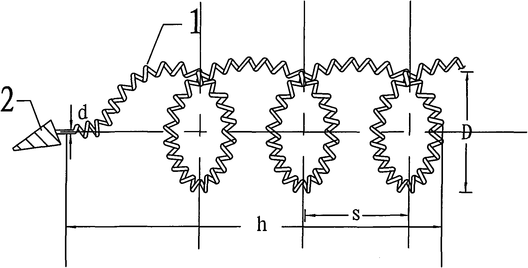
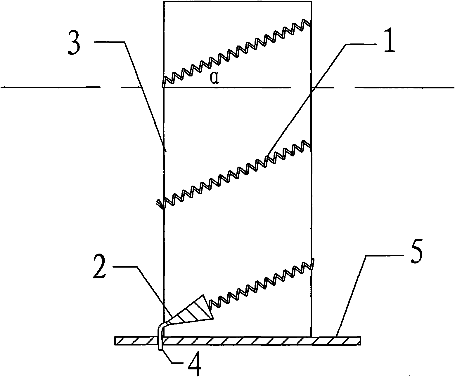
[0007] Specific implementation mode one: see figure 1 Illustrate this specific embodiment, a kind of small helical antenna, it comprises impedance converter 2, and it also comprises helical wire 1, and described helical wire 1 is wound into the antenna of helical shape, and one end of helical wire 1 and impedance converter 2 One end is connected, the number of helical turns of the helical antenna 2 is at least one cycle, and the helical rise angle of the helical antenna 2 is 5 degrees to 20 degrees.

[0008] The antenna of the present invention can be applied in the range of tens of megahertz to several gigahertz.

specific Embodiment approach 2

[0009] Embodiment 2: The difference between this embodiment and the small helical beam-focusing antenna described in Embodiment 1 is that the helical antenna has a helical diameter D, a helical circumference C, a pitch S, a helical rise angle α, The single turn length L, the number of turns N, the axial length h, and the diameter of the helical wire d satisfy the formula:

[0010] C=πD;

[0011] S=Ctanα;

[0012] α = arctan = S C ;

[0013] L = C 2 + S 2

[0014] h=NS

[0015] The helix diameter D is the distance between the centers of the coils of material.

[0016] Since the perimeter of the helical antenna is about one wavelength, the phases of the currents on the opposite sides of each circle are opposite, and each circle itself has a rev...

specific Embodiment approach 3

[0029] Embodiment 3: The difference between this embodiment and the small helical beam-focusing antenna described in Embodiment 1 or Embodiment 2 is that the helix angle of the spiral wire 1 is 12°-14°.


PUM


Abstract

The invention provides a small helical antenna, which relates to an antenna, and solves the problem of large volume of the existing helical antenna. The small helical antenna is formed by the winding of a helical wire; one end of the helical wire is connected with one end of an impedance transformer; the number of helical turns of the helical antenna is at least one; the helical climbing angle ofthe helical antenna is from 5 degrees to 20 degrees. The invention is suitable for satellites, airships, ballistic rockets, and the like and is applied to emitting or receiving circular polarization electromagnetic wave signals.

Description

technical field [0001] The invention relates to an antenna. Background technique [0002] There are three working modes of the helical antenna: normal mode, axial mode and side-firing mode. Among them, the axial mode is commonly used because of its high radiation efficiency and wide frequency band. The impedance in a large frequency band can be regarded as pure resistance. working mode. The axial mode can increase the gain by increasing the number of turns or arraying multiple helical antennas, which is often used in meter-wave and decimeter-wave communications. When the common single-wound axial mode helical antenna is working normally, the relationship between the wavelength λ corresponding to the radiation center frequency and the length L of each circle of the helical antenna is: 3 / 4<L / λ<4 / 3, due to the frequency f in vacuum There is a relationship between the wavelength λ and the speed of light c as follows: f·λ=c, where the speed of light c=3×10 8 m / s can be r...

Claims


Application Information

Patent Timeline
Patent Type & Authority Applications(China)
IPC IPC(8): H01Q1/36H01Q7/00
Inventor 宋朝晖张健路国明
Owner HARBIN INST OF TECH
Learn More