Air suction device for an air compressor

An air compressor and air suction device technology, applied to the components of the pumping device for elastic fluids, mechanical equipment, machines/engines, etc. The effect of reducing indoor noise and energy waste

Inactive Publication Date: 2009-11-04
SHENYANG ALUMINIUM MAGNESIUM INSTITUTE
View PDF0 Cites 2 Cited by
  • Summary
  • Abstract
  • Description
  • Claims
  • Application Information

AI Technical Summary

Problems solved by technology

[0004] 2. Affect the environment in the air compressor station
All of the above factors will make the operator feel uncomfortable

Method used


Image

  • Air suction device for an air compressor
  • Air suction device for an air compressor
  • Air suction device for an air compressor

Examples


Embodiment Construction

[0037] The present invention will be further described below in conjunction with the accompanying drawings, but the protection scope of the present invention is not limited by the embodiments.

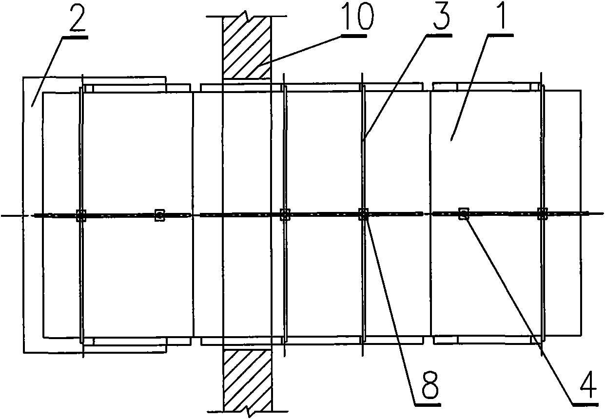
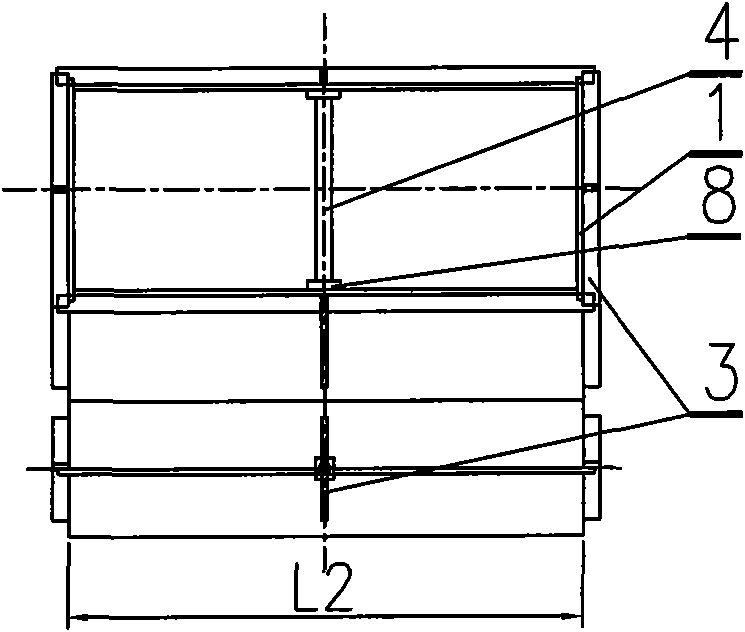
[0038] Such as Figure 1-6 As shown, the structure of the air compressor suction device of the present invention is as follows: one end of the suction pipe 1 is connected with the suction port of the air compressor, and the other end of the suction pipe 1 passes through the building wall 10 . The end of the suction pipe 1 that passes through the building wall 10 is provided with a filter screen 2, and the filter screen 2 is composed of a steel wire mesh 7 and a reinforced round steel 6 between the flat steel 5 on the upper and lower floors and the flat steel 5, and the bolts 9 fix the flat steel 5 and the wire mesh 7, and the round steel 6 and the upper flat steel 5 are welded together. Reinforcing ribs 3 are arranged on the outside of the suction pipe 1. The distance between the tran...


PUM


Abstract

The invention relates to an air suction device, in particular to an air suction device suitable for a screw type air compressor in a compressed air station. The air suction device for the air compressor is characterized in that one end of an air suction pipe is connected with an air suction opening of the air compressor, and the other end penetrates the external wall of a building. The invention has the advantages that the air suction device for the air compressor directly sucks air from the outdoor, thereby reducing the energy waste and the indoor noise.

Description

technical field [0001] The invention relates to an air suction device, in particular to an air suction device suitable for a screw air compressor in an air compressor station. Background technique [0002] For a long time, the screw air compressor in the air compressor station has been directly sucking air from the room. There are the following problems in this suction method: [0003] 1. Waste of energy. In winter, because the indoor intake air has taken away a large amount of heat, the indoor temperature is lowered, and only by increasing the heating and heat supply can the indoor temperature not be lowered. [0004] 2. Affect the environment in the air compressor station. The air flow of the compressor has pulsation, and the indoor air suction is generally provided with louvers on the wall of the building, which will generate noise when the air is inhaled. The above factors will make the operator feel uncomfortable. Contents of the invention [0005] In order to so...

Claims


Application Information

Patent Timeline
Patent Type & Authority Applications(China)
IPC IPC(8): F04C29/12
Inventor 袁琳瞿文军李玉峰
Owner SHENYANG ALUMINIUM MAGNESIUM INSTITUTE
Why Eureka
Try Eureka