Cable protection and guide device

A technology for guiding devices and cables, applied in drag chains, hanging chains, chain components, etc., which can solve the problems of increased production burden, labor consumption of side panels, insufficient flexural rigidity or torsional rigidity, and reduce the burden of assembly work , Lighten the load on parts assembly and suppress bending fatigue

Active Publication Date: 2009-10-28
TSUBAKIMOTO CHAIN CO
View PDF5 Cites 8 Cited by
  • Summary
  • Abstract
  • Description
  • Claims
  • Application Information

AI Technical Summary

Problems solved by technology

[0006] However, in the above-mentioned conventional cable protection and guide device 500, the pair of left and right side plate portions 510A, 510B each have a shape having three parts, the front side plate portion 511, the rear side plate portion 512, and the joint 513. Therefore, the side plate parts 510A and 510B are formed into complex shapes, which increases the manufacturing burden including molds.
[0007] In addition, since the side plate portions 510A and 510B are different parts independent of each other, it takes a lot of labor to connect them into a long strip shape, which is a labor force equal to the number of the side plate portions, which imposes a heavy burden on the assembly work.
[0008] Furthermore, the left and right pair of side plate parts 510A and 510B are in a mirror image relationship, so there is no compatibility between the left and right side plate parts 510A and 510B, and it is necessary to separate the left and right side plate parts 510A and 510B. Management, parts management is very complicated
[0009] In addition, since the connecting arm 520 made of polyamide resin is horizontally placed on the curved inner peripheral side and the curved outer peripheral side of a pair of left and right side plate parts 510A, 510B formed of polyamide resin arranged apart from each other, a cross-sectional rectangular shape is formed. Therefore, the cable storage space cannot be sufficiently ensured at the time of assembly due to the strong bonding force of the side plate portions 510A, 510B or insufficient flexural rigidity or torsional rigidity of the side plate portions 510A, 510B and the connecting arm 520 Stable rectangular cross-sectional shape, and when storing and guiding various cables in the manufacturing fields of food and semiconductors in a clean environment, it is necessary to fully consider the sliding contact with the cable C or the mutual sliding of the side plate parts 510A and 510B. Dust such as abrasion powder caused by contact, etc., and excessive bending fatigue of joint 513

Method used


Image

  • Cable protection and guide device
  • Cable protection and guide device
  • Cable protection and guide device

Examples


Embodiment 1

[0068] Below, combine Figure 1 to Figure 6 The cable protection guide device 100 which is Embodiment 1 of this invention is demonstrated.

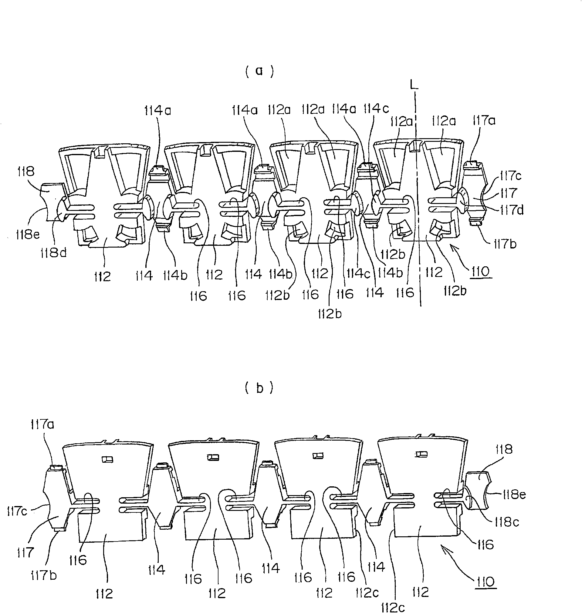
[0069] here, figure 1 is a perspective view showing a part of the cable protection and guide device 100 of this embodiment, figure 2 yes figure 1 An exploded view of the cable protection guide 100 is shown. image 3 is as figure 1 The perspective view of the link assembly 110 which is a component part of the shown cable protection guide apparatus 100, (a) is a perspective view seen from the cable storage space side, (b) is a perspective view seen from the outside. Figure 4 is as figure 1 The perspective view of the limiter chain link, which is a component of the cable protection and guide device 100 shown, (a) is a perspective view showing the side assembled on the link assembly, and (b) is viewed from the side of the cable storage space stereogram.

[0070] The cable protection and guiding device 100 of Embodiment 1 of the p...

Embodiment 2

[0102] Below, combine Figure 7 and Figure 8 The cable protection guide device 200 of Example 2 which is another embodiment of the present invention will be described.

[0103] here, Figure 7 is a perspective view showing a part of the cable protection and guide device 200 of this embodiment, Figure 8 yes Figure 7 An exploded view of the cable protection guide 200 is shown.

[0104] For the cable protection guide device 200 of this embodiment, such as Figure 7 and Figure 8 As shown, a link assembly 210 formed of a polyamide-based fatigue-resistant resin containing a rubber component is formed by integrally molding a plurality of side plate portions 212 via a joint portion 214 .

[0105] Such as Figure 8 As shown, the plurality of side plate portions 212 form an elongated link assembly 210 by connecting horizontally extending joint arms 216 to substantially diamond-shaped joint portions 214 formed between adjacent side plate portions 212 , 212 .

[0106] Such as ...

Embodiment 3

[0113] Below, use Figure 9 and Figure 10 The cable protection guide device 300 of Example 3 which is another embodiment of the present invention will be described.

[0114] here, Figure 9 is a perspective view showing a part of the cable protection and guide device 300 of this embodiment, Figure 10 yes Figure 9 An exploded view of the cable protection guide 300 is shown.

[0115] The cable protection guide device 300 of this embodiment, such as Figure 9 and Figure 10 As shown, a plurality of side plate portions 312 are integrally formed by means of joint portions 314 to form a chain link assembly 310 .

[0116] Such as Figure 10 As shown, these plurality of side plate portions 312 form an elongated link assembly 310 by connecting horizontally extending joint arms 316 to substantially diamond-shaped joint portions 314 formed between adjacent side plate portions 312 .

[0117] Such as Figure 10 As shown, the limiting chain link 320 made of polyacetal resin is a...


PUM


Abstract

A cable protection and guide device in which the number of parts used is reduced and assembly is simplified. Dust generation and bending fatigue is suppressed so that the cable protection and guide device exhibits excellent form stability of the cable accommodating space. Side plate portions and coupling portions are integrally molded from polyamide fatigue resistant resin into the form of a connecting link module. A polyacetal resin stopper link, which holds and limits the linear position and the bending position by engagement with the connecting link module, is inter-fitted with a coupling portion of the connecting link module by a snap-fit mechanism from the cable accommodating space side.

Description

technical field [0001] The present invention relates to a cable protection and guiding device. More specifically, it relates to accommodating cables such as cables or hoses for supplying energy such as electric power or compressed air to movable parts of industrial machinery, and relates to moving the movable parts. It is also possible to safely and reliably guide the cable protection guide device supporting the cables. Background technique [0002] As existing cable protection guides such as Figure 11 As shown, the following cable protection and guide device 500 is known. The cable protection and guide device 500 is configured such that a pair of left and right side plate parts 510A, 510B, which are arranged apart from each other, extend from the mounting fixed end to the mounting movable end, that is, in length A plurality of connected side plate parts 510A, 510B are connected in one direction, and the connecting arm 520 is spaced apart from each other, and a plurality of...

Claims


Application Information

Patent Timeline
Patent Type & Authority Applications(China)
IPC IPC(8): H02G3/04C08L77/00C08L21/00
CPCH02G3/0475F16G13/16Y10S59/90H02G11/006
Inventor 宇泷昭彦池田正明
Owner TSUBAKIMOTO CHAIN CO
Why Eureka
Try Eureka