


Quick Research
Generate reliable direction feasibility study reports for your R&D in just a few steps.

Technical Q&A
Discover and master advanced knowledge NOW. Basics, ideas, possibilities, all at once.

Find Solutions
As an expert in R&D theories, this can generate solutions to your technical problems instantly.

Evaluate Feasibility
Analyze your overall solution with one click, know your potential R&D risks in advance.

Monitor Landscape
Get weekly tech updates, stay abreast of the latest tech innovations and key insights.
Holding device
A clamping device and sleeve technology, applied in quenching devices, heat treatment equipment, furnaces, etc., can solve the problems of limited diameter range, inconvenient replacement of sleeves, processing constraints of workpieces with different diameters, etc., and achieve the effect of ensuring working life.
- Summary
- Abstract
- Description
- Claims
- Application Information
AI Technical Summary
Problems solved by technology
Method used
Image

Examples
Embodiment Construction
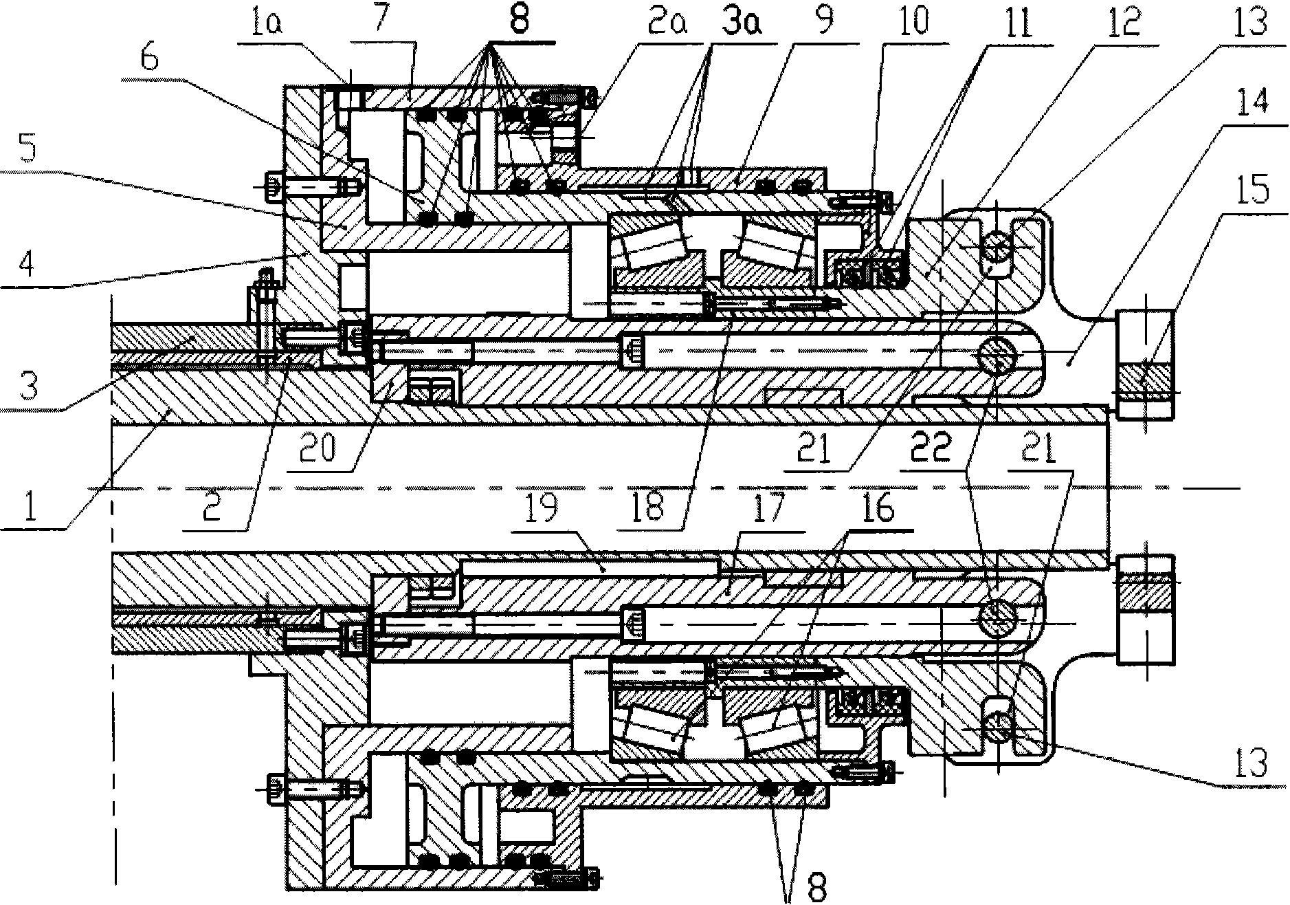
[0054] figure 1 is a cross-sectional view of a clamping device according to the invention. In the following description with figure 1 The right side is the front, and the left side is the back. As shown, the clamping device according to the invention comprises a hollow spindle 1 . During actual processing, the cooling medium—in this embodiment, cooling water—flows through the hollow part of the hollow spindle 1 into the interior of the quenched workpiece, thereby cooling the quenched workpiece from the inside.
[0055] The bearing sleeve 17 is arranged concentrically with the hollow spindle 1 . It can be seen from the figure that due to the needs of processing technology and installation, the supporting sleeve 17 and the sliding sleeve 12 are composed of multiple parts. But in this embodiment, for convenience of description, the combination of these parts is referred to as supporting sleeve 17 and sliding sleeve 12 according to their functions. The support sleeve 17 is ro...
PUM
 Abstract
Description
Claims
Application Information
 - R&D Engineer
- R&D Manager
- IP Professional
- Industry Leading Data Capabilities
- Powerful AI technology
- Patent DNA Extraction
Browse by: Latest US Patents, China's latest patents, Technical Efficacy Thesaurus, Application Domain, Technology Topic, Popular Technical Reports.
© 2024 PatSnap. All rights reserved.Legal|Privacy policy|Modern Slavery Act Transparency Statement|Sitemap|About US| Contact US: help@patsnap.com