
Resource monitoring method and device thereof

A technology of resource monitoring and resource occupation, applied in the direction of selection device, monitoring/monitoring/testing arrangement, digital transmission system, etc., can solve problems such as shortage, achieve improved centralization, improve maintainability and reliability, and reduce complexity and the effect of input costs

Inactive Publication Date: 2012-06-13
ZTE CORP
View PDF0 Cites 0 Cited by
  • Summary
  • Abstract
  • Description
  • Claims
  • Application Information

AI Technical Summary

Problems solved by technology

There is a lack of means for this in the current interface definition

Method used


Image

  • Resource monitoring method and device thereof
  • Resource monitoring method and device thereof
  • Resource monitoring method and device thereof

Examples


Embodiment Construction

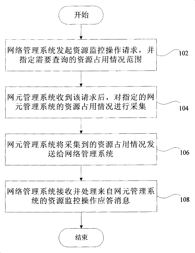
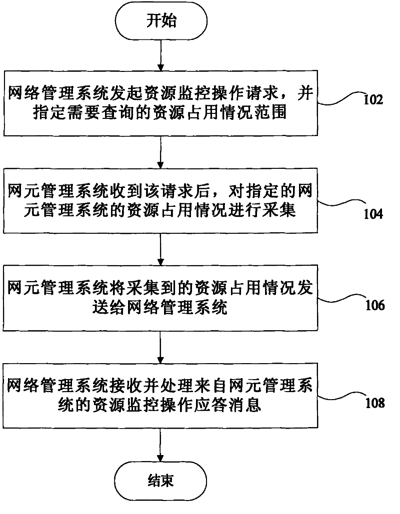
[0029] Such as figure 1 As shown, the resource monitoring method of the present invention specifically includes the following sequential steps:

[0030] In step 102, the network management system initiates a resource monitoring operation request, and specifies the range of resource occupancy to be queried. For example, the network management system initiates a resource monitoring operation request on the hard disk of the network element management system, and specifies that the hard disk capacity and free space of the hard disk need to be queried.

[0031] Step 104, after receiving the request, the network element management system collects the resource occupancy status of the specified network element management system; specifically, the method for collecting the resource occupancy status can be implemented by the network element management system itself. For example, after receiving the resource monitoring request of the hard disk, the network element management system coll...


PUM


Abstract

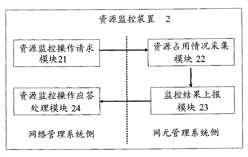
The invention relates to a resource monitoring method and a device thereof, wherein the device (2) comprises a resource monitoring operation requesting module (21), a resource occupying situation collecting module (22), a monitoring result reporting module (23) and a resource monitoring operation reply processing module (24); the resource monitoring method comprises the following steps: an NMS initiates a request of inquiring the occupying situation of network element manage system resource EMS; EMS receives the request and carries out the collection according to the request; the request is returned back to the NMS; and the NMS receives and processes the collected resource occupying situation. The method and the device ensure that the operation situation of the EMS system can be monitoredby the NMS, greatly improve the maintainability and the reliability of the whole network management, reduce the complexity and the input cost of the whole NMS and protect existing investment.

Description

technical field [0001] The invention relates to telecommunication network management, in particular to a resource monitoring method and device for telecommunication network management. Background technique [0002] The International Telecommunication Union (ITU) proposed the Telecommunications Management Network (TMN) in the mid-1980s, which is logically separated from the telecommunication network and uses standard interfaces (including communication protocols and information models). Transmit / receive management information with the telecommunication network to achieve the purpose of controlling and operating the telecommunication network. Its management system structure is relatively complicated. From the perspective of network layered management system structure, the management level of TMN is divided into five layers, which are as follows from low to high: Network Element Layer (NEL for short), network element management layer ( Element Management Layer (EML for short),...

Claims


Application Information

Patent Timeline
Patent Type & Authority Patents(China)
IPC IPC(8): H04L12/24H04M3/22H04Q3/00
Inventor 张凯
Owner ZTE CORP
Learn More