
Colored filter with grating structure

A color filter and grating structure technology, which is applied in the fields of holographic optics, diffractive optics and backlight display, can solve the problems that the performance of color filters needs to be further improved, the chromaticity of color filters is affected, and the utilization rate of light energy is not high. , to achieve the effect of improving the utilization rate of light energy, facilitating mass production, and facilitating design

Active Publication Date: 2009-09-30
SUZHOU UNIV +1
View PDF0 Cites 19 Cited by
  • Summary
  • Abstract
  • Description
  • Claims
  • Application Information

AI Technical Summary

Problems solved by technology

The design flaw is that different colors of transmitted light use different polarization states of incident light. Red light and green light use TM polarized light, and blue light uses TE polarized light, resulting in low light energy utilization efficiency.
[0006] (2) In the literature H.Lee, Y.Yoon, S.Lee, et.al.Color filter based on a subwavelength patterned metal grating [J]. Optics Express, 2007, 23 (15): 15457-15463 discloses the use of The grating structure of the two-dimensional metal Al grating covered with a dielectric layer is used to design the color filter. The disadvantage is that its transmission spectral bandwidth is greater than 150nm, which affects the chromaticity of the color filter.
[0007] (3) Disclosed in the literature Y.Yoon, H.Lee, S.Lee, et.al.Color filter incorporating a subwavelength patterned grating in poly silicon [J]. Optics Express, 2008, 4(16): 2374-2380 A color filter, using quartz as the substrate, polysilicon grating and silicon dioxide layered with the same width, and air to form the grating area, its disadvantage is that the spectral transmittance is low
[0008] It can be seen that with the continuous deepening of market applications, color filters are developing towards large format and high light energy utilization. The development of color filters based on grating structures has become a hot spot, and the currently published color filters based on grating structures Performance needs to be further improved

Method used


Image

  • Colored filter with grating structure
  • Colored filter with grating structure
  • Colored filter with grating structure

Examples


Embodiment 1

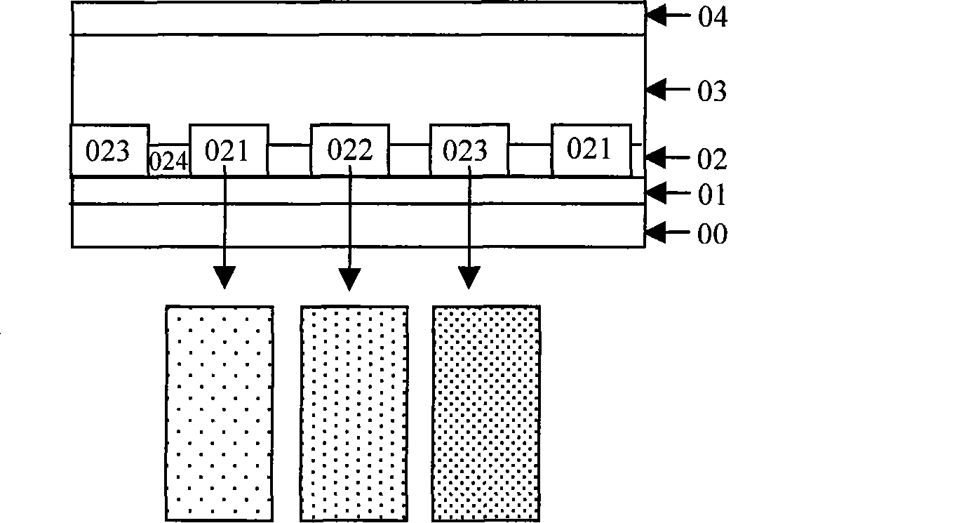
[0037] Embodiment 1: a kind of color filter, the structure sees attached figure 1 As shown, 00 is the glass substrate, 01 is the SiO2 film, 02 is the color layer, 03 is the protective film, and 04 is the transparent conductive film. 021, 022 and 023 are red, green and blue three-color color units respectively, which are composed of two-dimensional submicron metal gratings with different space frequencies.

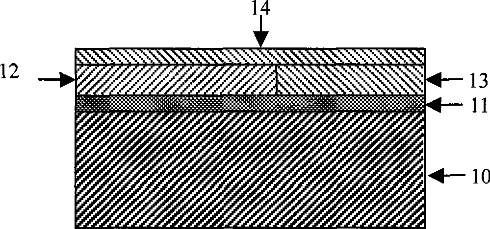
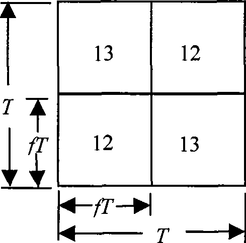
[0038] Among them, the two-dimensional submicron embedded metal grating structure can be found in the attached figure 2 And attached image 3 As shown: the substrate 10 is a transparent material such as glass, quartz, PMMA or PET, the film layer 11 is a high refractive index medium, and its refractive index is greater than 1.65, the grating area is composed of a metal 12 and a low refractive index medium 13, and the metal 12 is Au , Al, Ag and other materials, the refractive index of the medium 13 is less than 1.65, the film layer 14 is a low refractive index material, a...

Embodiment 2

[0041] Embodiment two: see attached figure 2 As shown, a color filter, the structure is similar to the first embodiment, the thickness of the film layer 14 is zero, the thickness of the film layer 11 is 30nm, when the depth of the grating 12 is 65nm, the duty ratio f is 0.5, and the grating period is 240nm, the transmission spectrum is the broadband bandpass filter output in the wavelength range of 400-500nm, the maximum transmittance is 70%, see the attached Figure 8 ; When the duty cycle is 0.56 and the period T is 340nm, the transmission spectrum is the broadband bandpass filter output in the wavelength range of 500-600nm, and the maximum transmittance is 78%. Figure 9 ; When the duty cycle is 0.55 and the period T is 420nm, the transmission spectrum is the broadband bandpass filter output in the wavelength range of 600-700nm, and the maximum transmittance is 71%. Figure 10 .

Embodiment 3

[0042] Embodiment three: a kind of color filter, structure sees attached figure 2 As shown, the film layer 11 is TiO 2 The film and the grating area 12 are metal Al, when the thickness of the film layer 14 is 10nm, the duty cycle f is 0.5, the thickness of the film layer 11 is 30nm, the depth of the grating 12 is 60nm, and when the grating period T is 240nm, the transmission spectrum is the wavelength Broadband bandpass filtered output in the range 400-500nm with a maximum transmittance of 68%, see attached Figure 11 When the duty cycle f is 0.55, the thickness of the film layer 11 is 30nm, the depth of the grating 12 is 70nm, and the grating period T is 330nm, the transmission spectrum is a broadband bandpass filter output in the wavelength range of 500-600nm, and the transmittance is the largest value is 75%, see attached Figure 12 When the duty cycle f is 0.58, the thickness of the film layer 11 is 50nm, the depth of the grating 12 is 70nm, and the grating period T is ...


PUM

PropertyMeasurementUnit
Grating constantaaaaaaaaaa

Abstract

The invention discloses a colored filter with a grating structure, which mainly comprises a substrate, a black matrix, a color filter layer, a protective layer and an ITO conducting film and is characterized in that the substrate is covered with a dielectric layer, the refractive index of the dielectric layer is larger than 1.65, the color filter layer is an embedded submicron grating which consists of a metal layer and a low-index dielectric layer, the metal layer is arranged at one side close to the substrate, the low-index dielectric layer is arranged at one side far from the substrate, and the refractive index of dielectric material is smaller than 1.65; and grating units of different colors are obtained by different grating structural parameters. The invention is based on the submicron embedded metal grating structure, has same transmitted spectrum characteristic under TE and TM polarized lights, has high utility rate of luminous energy, improves the purity of output light and can be manufactured in super large breadth.

Description

technical field [0001] The invention relates to an optical device, in particular to a color filter (Color Filter, CF), which can be used for a liquid crystal flat panel display and belongs to the fields of holographic optics, diffractive optics and backlight display. Background technique [0002] Color filter is a key component of liquid crystal display (Liquid Crystal Display) colorization. Liquid crystal flat panel display is a non-active light-emitting element, which provides light source through the internal backlight module (transmissive LCD) or external ambient incident light (reflective or semi-transmissive LCD), with a driver IC (Drive IC) and The liquid crystal (Liquid Crystal) is controlled to form a grayscale display (Gray Scale), and then through the R, G, and B color layers of the color filter to provide the hue (Chromacity) to form a color display screen. The structure of the color filter and the quality of the light guiding performance have a decisive impact ...

Claims


Application Information

Patent Timeline
IPC IPC(8): G02B5/20G02F1/1335
Inventor 叶燕陈林森周云张恒浦东林
Owner SUZHOU UNIV
Learn More