
Planetary-harmonic composite gear reducer

A gear reducer, planetary harmonic technology, applied in the direction of gear transmission, belt/chain/gear, mechanical equipment, etc., can solve the problems of large axial size, small reduction ratio, large volume, etc., and achieve small axial size , The effect of large reduction ratio and small volume

Active Publication Date: 2009-09-30
成都川哈工机器人及智能装备产业技术研究院有限公司
View PDF0 Cites 14 Cited by
  • Summary
  • Abstract
  • Description
  • Claims
  • Application Information

AI Technical Summary

Problems solved by technology

[0003] The purpose of the present invention is to provide a planetary harmonic compound gear reducer to solve the problems of small reduction ratio, large axial size, large volume, and large quality in the existing cup-shaped harmonic reducer.

Method used


Image

  • Planetary-harmonic composite gear reducer
  • Planetary-harmonic composite gear reducer

Examples


specific Embodiment approach 1

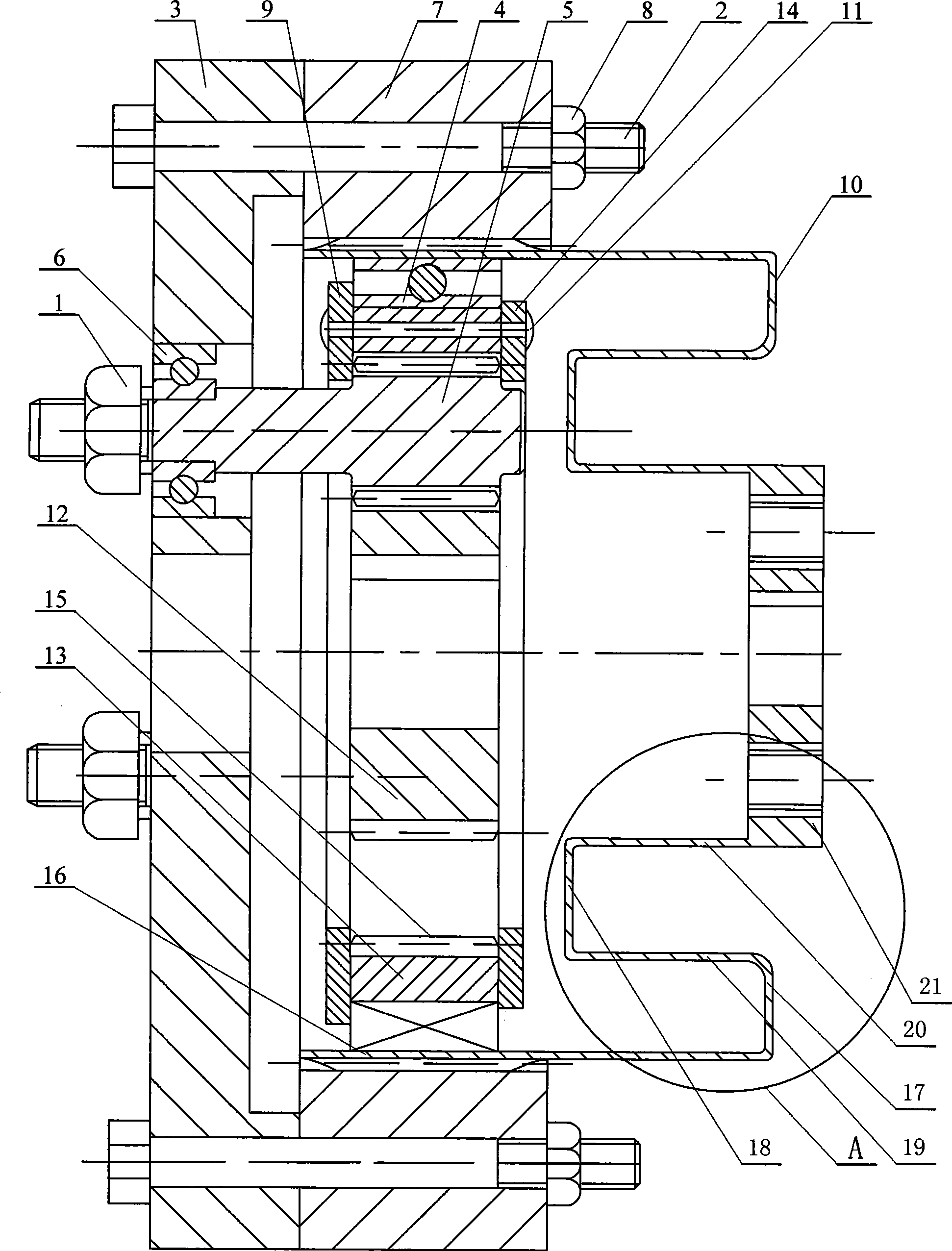
[0007] Specific implementation mode 1: Combination figure 1 with figure 2 To illustrate this embodiment, the reducer of this embodiment includes an elliptical cam 13 and a flexible ball bearing 4; the reducer of this embodiment also includes a planetary gear shaft nut 1, two tie rod fixing bolts 2, a tie rod 3, at least two A planetary gear shaft 5, at least two rolling bearings 6, a rigid inner ring gear 7, two tie rod fixing nuts 8, a large annular stopper 9, a small annular stopper 14, a flexible gear 10 and a sun gear 12; the ellipse The center of the cam 13 is provided with an elliptical hole, the inner wall of the elliptical hole is machined with teeth to form an elliptical inner ring gear 15, the sun gear 12 and at least two planets evenly arranged along the circumference of the sun gear 12 The gears on the gear shaft 5 mesh with each other, the sun gear 12 and at least two planetary gear shafts 5 are placed in the elliptical ring gear 15 of the elliptical cam 13, and the ...

specific Embodiment approach 2

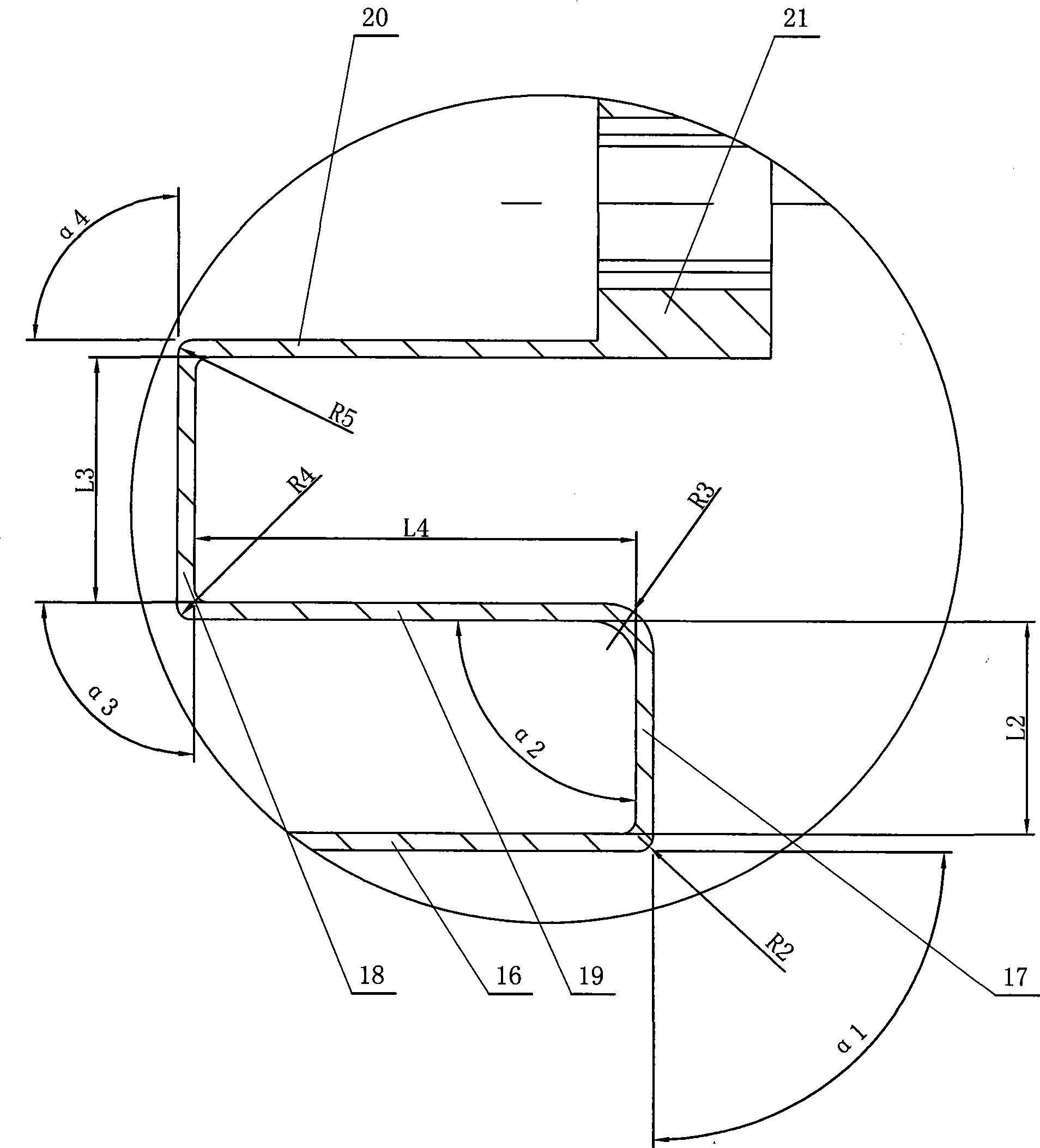
[0008] Specific implementation manner two: combination figure 1 with figure 2 To illustrate this embodiment, the flexible gear 10 of this embodiment is composed of an integrated outer gear sleeve 16, a large annular plate 17, a small annular plate 18, an intermediate thin-walled sleeve 19, an inner thin-walled sleeve 20, and an end cover 21. The large annular plate 17 is installed in the outer tooth sleeve 16, the outer circumferential end surface of the large annular plate 17 is fixed to the inner wall of one end of the outer tooth sleeve 16, and the middle thin-walled sleeve 19 is installed in the outer tooth sleeve 16, and the middle is thin One end of the wall sleeve 19 is installed in the central hole of the large annular plate 17, the outer wall of the middle thin-wall sleeve 19 is fixedly connected to the inner wall of the central hole of the large annular plate 17, and the small annular plate 18 is installed in the middle thin-wall sleeve 19, the outer circumferential end...

specific Embodiment approach 3

[0009] Specific implementation mode three: combination figure 1 The present embodiment will be described. The number of teeth of the flexible gear 10 of the present embodiment is two less than the number of teeth of the rigid ring gear 7. With this arrangement, when the wave generator rotates once, the flexible gear 10 drives the rigid ring gear 7 to rotate through the angle of two teeth in the opposite direction, thereby realizing a large transmission ratio. Others are the same as the first or second embodiment.


PUM


Abstract

The invention relates to a planetary-harmonic composite gear reducer, which relates to a reducer, and aims at the problems that the prior cup-shaped harmonic reducer has small reduction ratio, large axial size, large volume, large mass and the like. A sun gear is engaged with at least two planetary gear shafts and is arranged in an elliptical internal gear ring of an elliptical cam, the at least two planetary gear shafts are engaged with the elliptical internal gear ring of the elliptical cam to form a primary planetary reduction gear train, the elliptical cam is arranged in a flexible ball bearing, the primary planetary reduction gear train and the flexible ball bearing form a wave generator, the flexible ball bearing is arranged in a flexible gear, the flexible gear is arranged in a rigid internal gear ring and is engaged with the rigid internal gear ring under the action of the wave generator, and a planetary gear shaft arranged in a shaft hole of a tie bar is provided with a rolling bearing. The reducer has the advantages of large reduction ratio, small axial size, small volume, light mass and the like, and is particularly suitable to be applied in the fields such as aviation and space detectors, various instruments and meters, and driving units of precision robots and the like.

Description

Technical field [0001] The invention relates to a reducer. Background technique [0002] At present, for a specific type of cup-type harmonic reducer, there are small reduction ratios, large axial dimensions (the axial dimension of the cup-type harmonic reducer is basically the same as the inner diameter of the flexible gear), large volume, and large mass. And other issues. For example, for a standard type 32 cup type harmonic reducer, the basic size of the flexible gear is approximately: inner diameter d r =32mm, cylinder length L=30mm, maximum reduction ratio is 80. The axial size of the flexible gear severely limits the application of the cup-shaped harmonic reducer in the fields of aerospace detectors, various instruments and meters, and drive units of precision robots. Summary of the invention [0003] The purpose of the present invention is to provide a planetary harmonic compound gear reducer to solve the problems of small reduction ratio, large axial size, large volume, ...

Claims


Application Information

Patent Timeline
Patent Type & Authority Applications(China)
IPC IPC(8): F16H37/12
CPCF16H1/2818
Inventor 邓宗全高海波王迪陶建国
Owner 成都川哈工机器人及智能装备产业技术研究院有限公司
Learn More