
Structure of spiral-flow aeration sedimentation sewage treatment tank and using method thereof

A sewage treatment tank and aeration technology, applied in the direction of aerobic and anaerobic process treatment, etc., can solve the problems of the treatment system not working normally, increase the hydraulic load of the sedimentation tank, increase the total sludge volume of the sedimentation tank, etc., and achieve the reduction of sewage The circulation and operation link, increasing the depth of the pool, and improving the effect of aeration efficiency

Inactive Publication Date: 2009-09-23
SHANGHAI NENGZHENG FISHING TECH DEV CO LTD
View PDF0 Cites 6 Cited by
  • Summary
  • Abstract
  • Description
  • Claims
  • Application Information

AI Technical Summary

Problems solved by technology

Activated sludge is a new force to remove pollutants. The processing capacity of the sewage treatment mixing system will increase with the increase of the concentration of activated sludge in the sewage treatment mixing system, but the increase of the return sludge flow increases the hydraulic load of the sedimentation tank, and also increases The total amount of sludge entering the sedimentation tank will increase the concentration of floating solids in the effluent of the sedimentation tank. In severe cases, the entire treatment system will not work properly.

Method used


Image

  • Structure of spiral-flow aeration sedimentation sewage treatment tank and using method thereof
  • Structure of spiral-flow aeration sedimentation sewage treatment tank and using method thereof
  • Structure of spiral-flow aeration sedimentation sewage treatment tank and using method thereof

Examples


Embodiment Construction

[0031] Aiming at the deficiencies of the conventional floating growth method bioreactor, the present invention provides a kind of floating growth method bioreactor which can make the activated sludge reflux in the reactor, which can improve the microbial concentration and sewage treatment capacity in the bioreactor, and reduce the The return flow operation of the sludge in the sedimentation tank simplifies the operation and saves energy. The micro-flow operation in the later stage of the cyclone sedimentation treatment is beneficial to the sedimentation of the activated sludge and improves the effluent water quality of the sewage treatment tank.

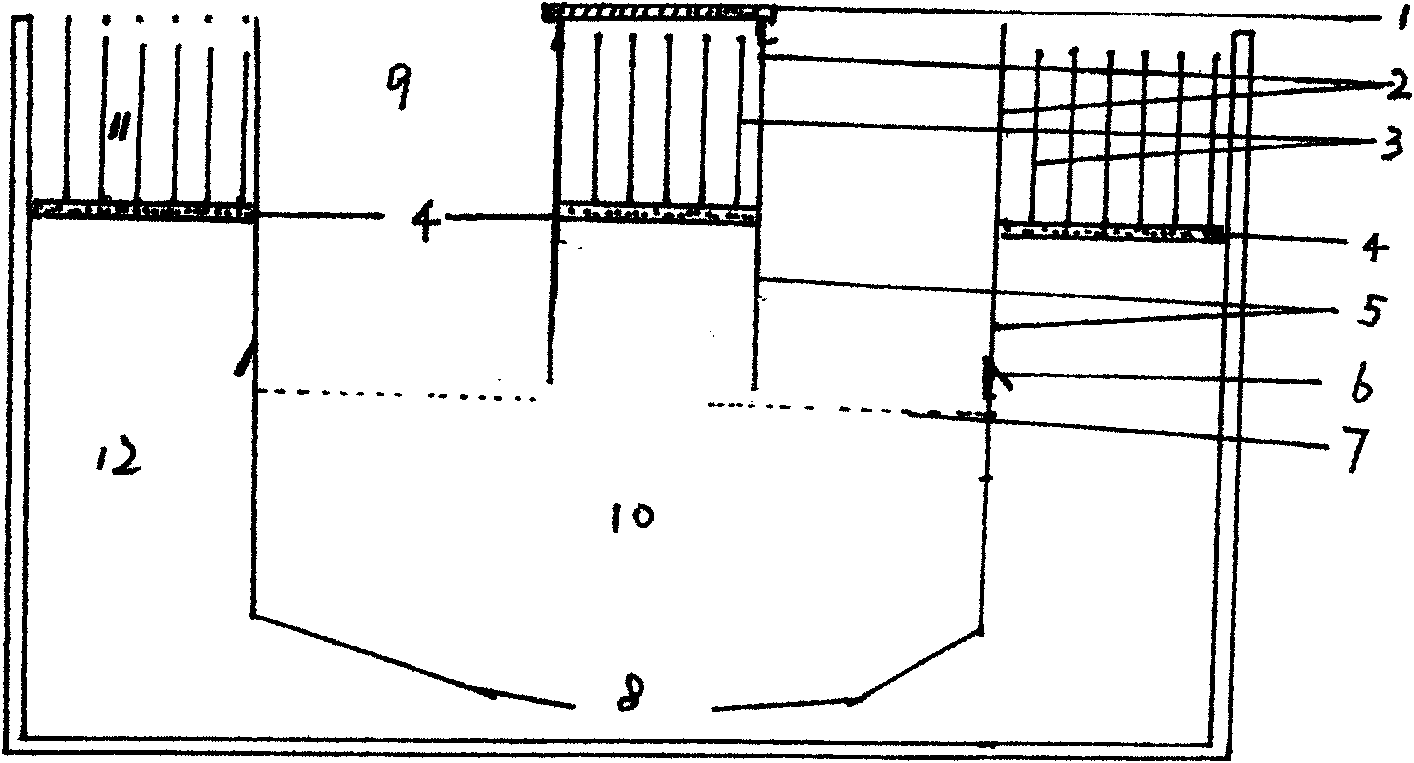
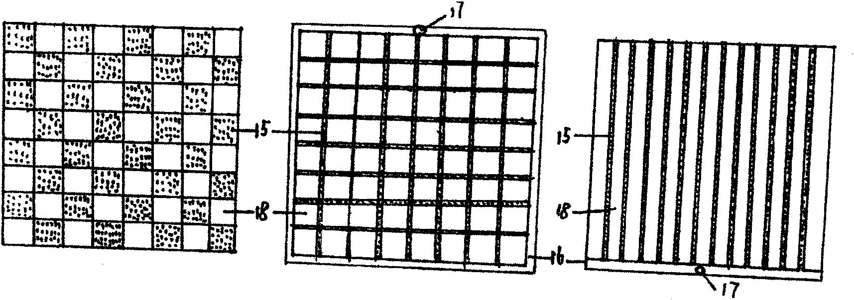
[0032] The structure and use method of the cyclone aeration sedimentation sewage treatment tank: the main process of air flotation separation and biological treatment is organically combined in one container, and fixed water pumping and aeration devices 14 are installed at the four corners or around the container to selectively The se...


PUM


Abstract

The invention relates to a structure of a spiral-flow aeration sedimentation sewage treatment tank and a using method thereof to organically combine main technological processes of air flotation separation and biological treatment into a container, wherein the four corners or the periphery of the container are provided with a fixed water-raising aerating apparatus and the middle part of the container is provided with a floating water-raising aerating apparatus; the sewage at a bottom layer is aerated selectively, and the sewage in the container is aerated circularly and alternately at the same time; the water-raising aerating apparatus is formed by mounting a gapped combined aerator in a vertical pipe frame; the fixed water-raising aerating apparatus and the floating water-raising aerating apparatus can be used singly or together; the water-raising aerating apparatuses stir and mix the sewage in the container and make use of deep drainage to aerate the sewage circularly and alternately; after a period of time of aeration treatment, membrane holes under middle-layer membranes are opened, the clearances among the middle-layer membranes are furled, aerobic treatment is performed on the sewage above the middle-layer membrane, and anaerobic treatment is performed on the sewage below the middle-layer membrane; and the sewage and most of activated sludge after the treatment are discharged, and a new sewage treatment cycle is restarted.

Description

(1) Technical field [0001] The present invention relates to a sewage and waste water treatment device and use method, more precisely, the present invention is applicable to the treatment device and use method for biological treatment of sewage and waste water under aerobic, anoxic and anaerobic conditions simultaneously. (2) Background technology [0002] The earliest combined sewage treatment complete mixing system is generally a circular pool. The middle of the pool is a fully mixed aerated biochemical area, the outside is a diversion area and a sedimentation area, and there is a sludge return slot at the bottom. This is a small system. , the concentration of pollutants in the aeration zone is equivalent to the concentration of the sedimentation and removal water after treatment. Therefore, the combined sewage treatment complete mixing system has low efficiency, poor effect, large floor area, and low promotion and use value. [0003] The existing ordinary activated sludge ...

Claims


Application Information

Patent Timeline
IPC IPC(8): C02F3/30
Inventor 阳清发
Owner SHANGHAI NENGZHENG FISHING TECH DEV CO LTD
Learn More