
Fuel cell system

A fuel cell system and fuel cell technology, applied in the direction of fuel cells, fuel cell additives, solid electrolyte fuel cells, etc., can solve the problems of taking too much time and not being able to start well

Inactive Publication Date: 2009-09-16
TOYOTA JIDOSHA KK
View PDF1 Cites 20 Cited by
  • Summary
  • Abstract
  • Description
  • Claims
  • Application Information

AI Technical Summary

Problems solved by technology

If the fuel cell is placed in a low-temperature environment below 0°C from the time the system is stopped until the next system startup, the next system startup will not be performed properly due to the influence of the frozen product water in the fuel cell, or take more time

Method used


Image

  • Fuel cell system
  • Fuel cell system
  • Fuel cell system

Examples


Embodiment Construction

[0049] A fuel cell system according to a best embodiment of the present invention will be described below with reference to the drawings.

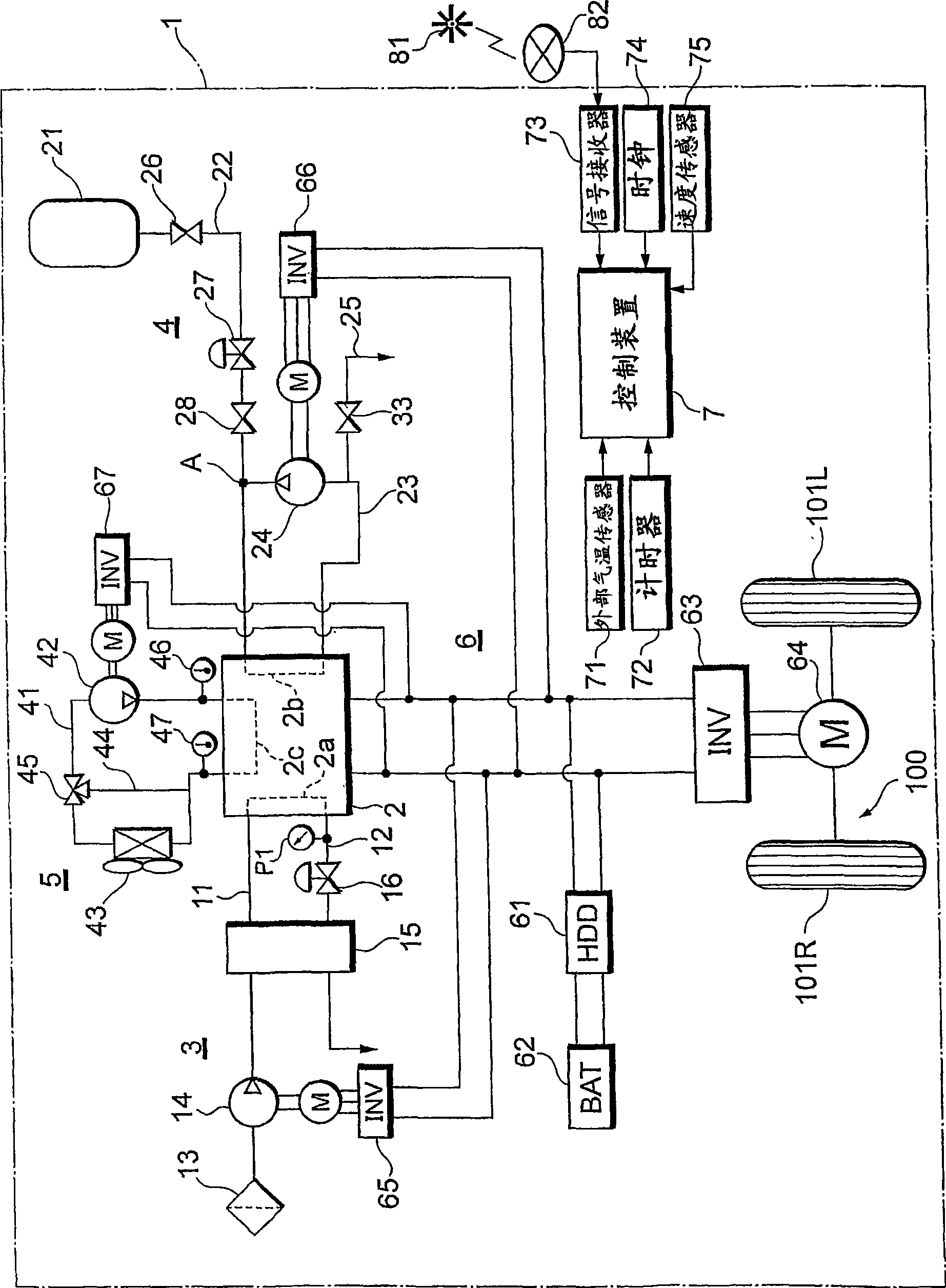
[0050] Such as figure 1 As shown, the fuel cell system 1 can be mounted on a vehicle 100 such as a fuel cell vehicle (FCHV), an electric vehicle, or a hybrid vehicle. However, the fuel cell system 1 can also be applied to various mobile bodies (for example, ships, airplanes, robots, etc.) and stationary power sources other than the vehicle 100 .

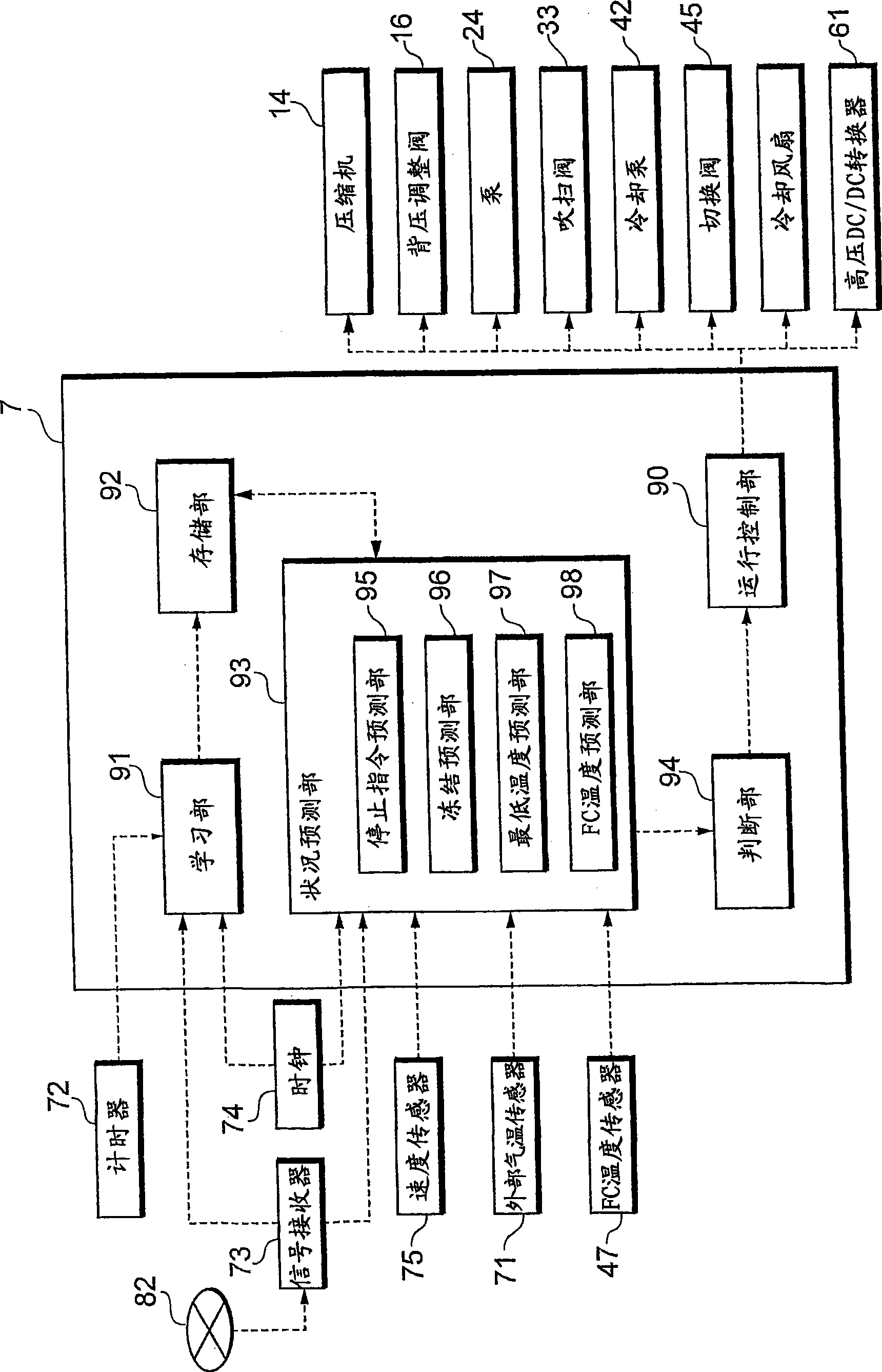
[0051] The fuel cell system 1 includes a fuel cell 2, an oxidizing gas piping system 3 for supplying air as an oxidizing gas to the fuel cell 2, a fuel gas piping system 4 for supplying hydrogen gas as a fuel gas to the fuel cell 2, and a piping system for supplying a refrigerant to the fuel cell 2. The refrigerant piping system 5 , the power system 6 for charging and discharging electric power for the system 1 , and the control device 7 for overall controlling the operation of the system 1 . T...


PUM


Abstract

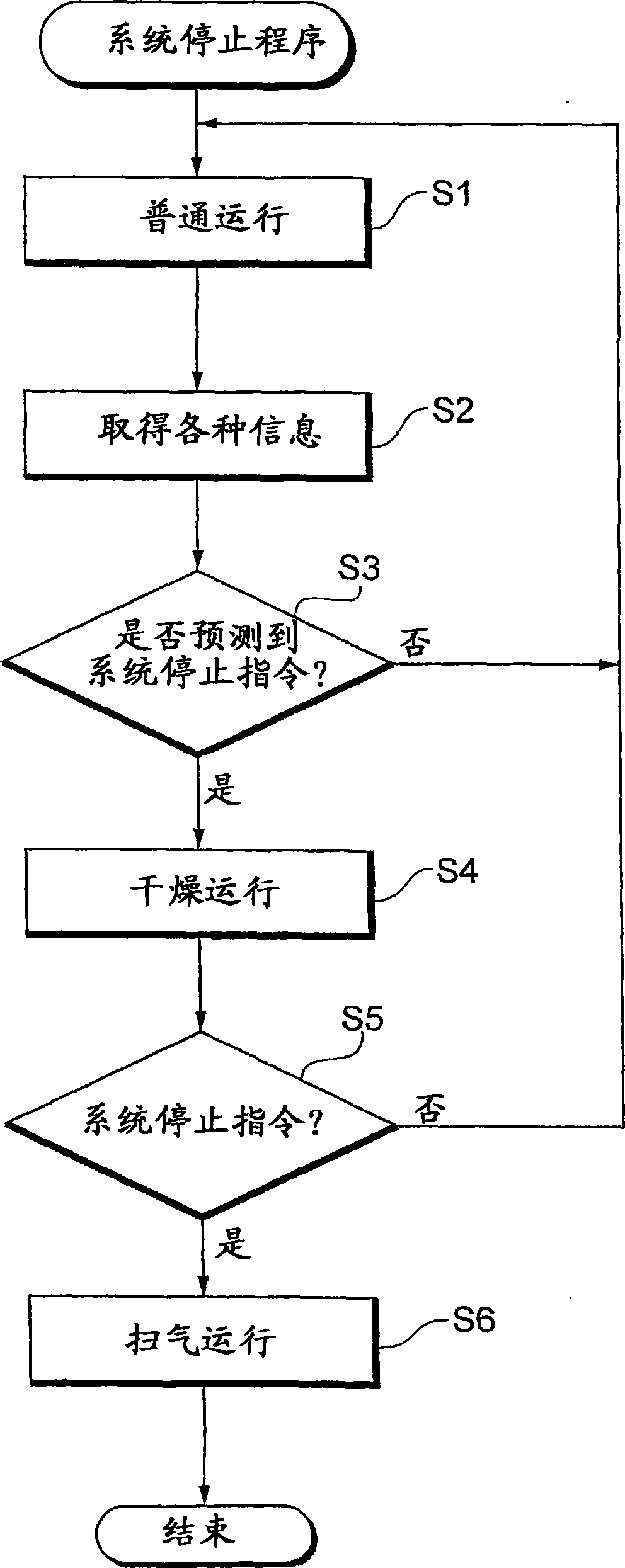
It is possible to provide a fuel cell system capable of drying a fuel cell in a short time after a system stop instruction is issued. The fuel cell system includes a control device controlling execution of a normal operation and a dry operation which reduces the water content of the fuel cell as compared in the normal operation. The control device executes the dry operation prior to the system stop instruction so that the water content of the fuel cell is reduced as compared to the normal operation upon a system stop instruction. The control device may execute the dry operation before the system stop instruction when the temperature of the fuel cell at the system stop or the next system start is expected to be a predetermined low temperature.

Description

technical field [0001] The present invention relates to a fuel cell system including a fuel cell, and particularly relates to control for reducing the water content of the fuel cell when the system is stopped. Background technique [0002] A solid polymer fuel cell generates electricity through a chemical reaction of hydrogen in a fuel gas supplied to the anode and oxygen in an oxidizing gas supplied to the cathode. In this electrochemical reaction, water is produced on the cathode side. If the fuel cell is placed in a low-temperature environment below 0°C after the system is stopped until the next system start-up, the next system start-up will not be performed properly due to the influence of the frozen product water in the fuel cell, or It takes more time. [0003] Japanese Patent Application Laid-Open No. 2005-251576 discloses a control method for reducing the water content of the fuel cell when the system is stopped while ensuring stable startability even in a low-temp...

Claims


Application Information

Patent Timeline
Patent Type & Authority Applications(China)
IPC IPC(8): H01M8/04H01M8/00H01M8/10
CPCH01M8/04761H01M8/04156H01M8/0488H01M8/0441H01M8/04373H01M8/04223H01M8/04828H01M8/04358Y02E60/50H01M8/04753H01M8/04559H01M8/04567B60L2240/12B60L58/31H01M8/04228Y02T90/40H01M8/04H01M8/10
Inventor 田中泰明渡边一裕
Owner TOYOTA JIDOSHA KK
Learn More