
Circuit and method for short-circuit protection of light-emitting diode (LED) lightbars

A technology for short-circuit protection circuits and light-emitting diodes, which is applied to emergency protection circuit devices, emergency protection devices with automatic disconnection, circuit devices, etc., and can solve problems such as undetectable, undetectable voltage of light-emitting diodes, serial burnout, etc.

Inactive Publication Date: 2009-09-16
INNOLUX CORP
View PDF7 Cites 31 Cited by
  • Summary
  • Abstract
  • Description
  • Claims
  • Application Information

AI Technical Summary

Problems solved by technology

However, since the LEDs exist in series, when one of the LEDs in the series is damaged and a short circuit occurs, it will cause high current and high voltage drop to gather on the control integrated circuit, causing the entire series to burn out
[0004] Since the existing technology cannot detect the voltage of a single light-emitting diode short-circuit, the existing method is to set a fixed voltage in the control integrated circuit. Once the detected voltage is greater than the fixed voltage, the It shuts down (shoutdown) to protect the series of light-emitting diodes; however, due to the forward voltage of the light-emitting diodes (V F ) has a large range, from 2.8V to 3.6V, which makes it difficult to determine the fixed voltage point of protection. If the setting is too high, it is easy to cause undetectable problems, and if the setting is too low, it is easy to cause misjudgment problems; moreover, Since the forward voltage of the LED is susceptible to fluctuating due to temperature, it will lead to misjudgment, and this phenomenon will also cause the LED to be shut down under normal operation.

Method used


Image

  • Circuit and method for short-circuit protection of light-emitting diode (LED) lightbars
  • Circuit and method for short-circuit protection of light-emitting diode (LED) lightbars
  • Circuit and method for short-circuit protection of light-emitting diode (LED) lightbars

Examples


Embodiment Construction

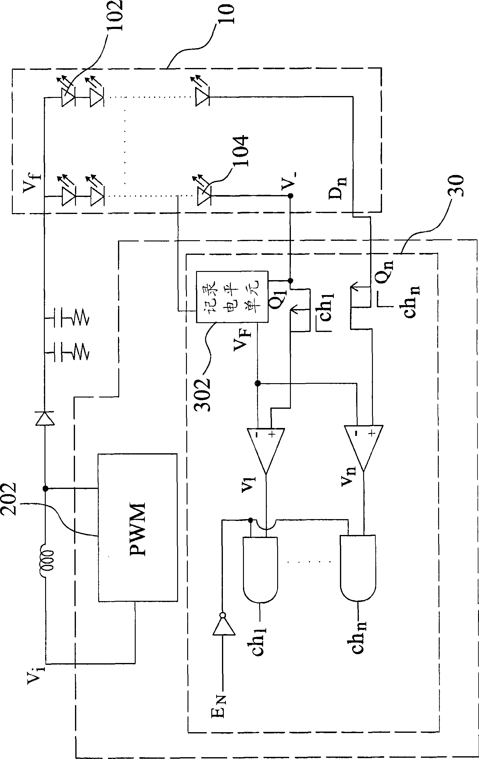
[0023] The short-circuit protection circuit and method of the LED lightbar proposed by the present invention utilizes the feedback of at least one LED in the LED string as the adjustment reference of the protection voltage, so that the light-emitting diodes selected by the display panel can be adjusted accordingly. Diode forward voltage (V F ) to determine the forward reference voltage of the protection voltage. Furthermore, the forward reference voltage can be automatically and dynamically adjusted according to the temperature rise or fall.

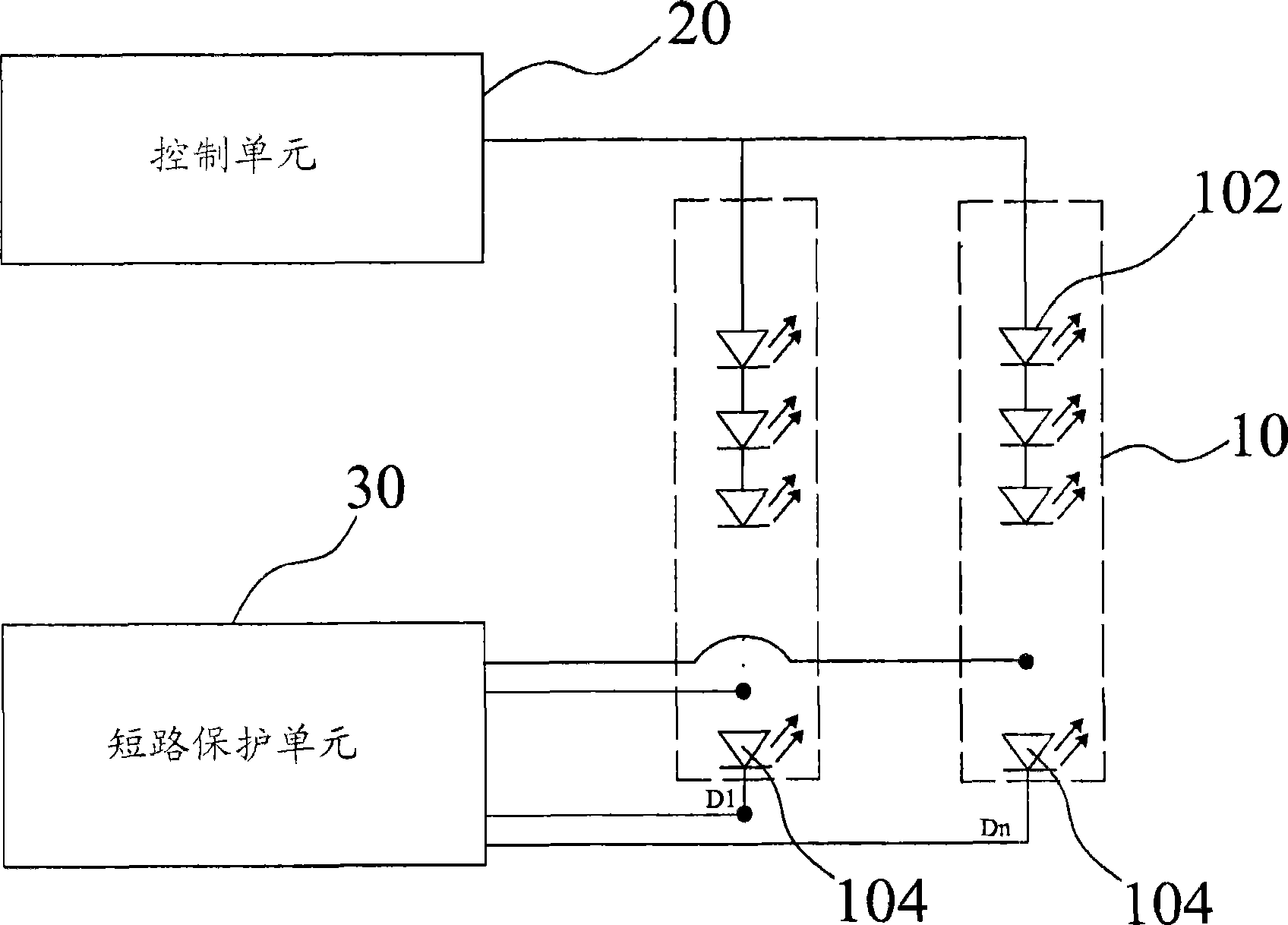
[0024] Please refer to figure 1 As shown, the short-circuit protection circuit of the light-emitting diode series includes three parts: one or more light-emitting diode series 10, a control unit 20, and a short-circuit protection unit 30. The multiple light-emitting diode series 10 shown in the figure serve as For the backlight source of the liquid crystal display panel, each light emitting diode string 10 is formed by a plurality of li...


PUM


Abstract

The invention discloses a circuit and a method for short-circuit protection of light-emitting diode (LED) lightbars. At least one LED lightbar is taken as a backlight source; each lightbar consists of a plurality of LEDs; furthermore, the LED lightbar is driven and provided by a control unit; a short circuit protection unit can protect the LED lightbar; and the short circuit protection unit is electrically connected with two ends of the LEDs of the LED lightbar so as to obtain the measured voltage, thus judging whether the short circuit of the LED occurs according to the measured voltage and a forward benchmark voltage. As the circuit and the method can dynamically adjust the forward benchmark voltage of the protection voltage and avoid the mistaken judgment, thus avoiding the circuit from being burned more effectively.

Description

technical field [0001] The invention relates to short-circuit protection circuit technology, in particular to a short-circuit protection circuit for series of light-emitting diodes and a method thereof. Background technique [0002] Due to the advancement of LED technology, LED applications are becoming more and more diversified. Using LEDs as display backlights and lighting equipment has become a hot topic recently. Compared with the traditional cold cathode tube (CCFL), it has more advantages in terms of power consumption and environmental protection requirements, so it is widely used. [0003] Taking light-emitting diodes as the backlight source of the display panel as an example, it mainly includes a plurality of light-emitting diode strings, each light-emitting diode string is composed of a plurality of light-emitting diodes, and a control integrated circuit (Control IC) is used to control the light-emitting diodes. The operation of the diode string is effective as a b...

Claims


Application Information

Patent Timeline
Patent Type & Authority Applications(China)
IPC IPC(8): H05B37/03H05B37/02H02H3/087
Inventor 杨政峰
Owner INNOLUX CORP
Learn More