Eureka AIR delivers breakthrough ideas for toughest innovation challenges, trusted by R&D personnel around the world.

Millimeter-wave four-polarized frequency scanning antenna

A frequency-scanning antenna and four-polarization technology, which is applied to antenna unit combinations with different polarization directions, slot antennas, circuits, etc., can solve the problems of circularly polarized beam scanning difficulties and achieve low loss, large power capacity, and mutual coupling effect

Active Publication Date: 2012-07-25
SOUTHEAST UNIV
View PDF4 Cites 0 Cited by
  • Summary
  • Abstract
  • Description
  • Claims
  • Application Information

AI Technical Summary

Problems solved by technology

It is very difficult to scan circularly polarized beams, mainly because it cannot guarantee excellent axial ratio characteristics in a wide scanning range

Method used


Image

  • Millimeter-wave four-polarized frequency scanning antenna
  • Millimeter-wave four-polarized frequency scanning antenna

Examples


Embodiment Construction

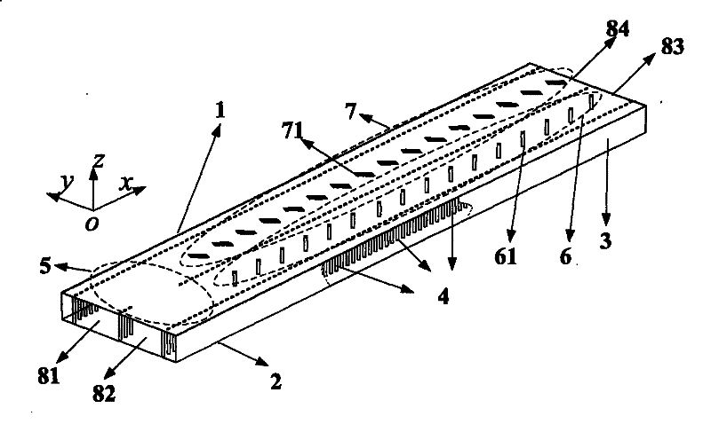
[0019] The millimeter wave quad-polarized frequency scanning antenna in the present invention includes an upper metal copper-clad surface 1, a lower metal copper-clad surface 2, a dielectric substrate 3, a metalized through hole 4, a substrate integrated waveguide 90° directional coupler 5, a base Chip integrated waveguide 16-slot 45° slot array leaky wave antenna 6, Substrate integrated waveguide 16-slot-45° slot array leaky wave antenna 7, input port 81, input port 82, input port 83, input port 84; copper-clad upper metal The surface 1 and the lower metal copper-clad surface 2 are respectively located on the front and back sides of the dielectric substrate 3, and the metallized through holes 4 pass through the dielectric substrate 3 to connect with the upper metal copper-clad surface 1 and the lower metal copper-clad surface 2 to form a base. Chip integrated waveguide 90° directional coupler 5. Substrate integrated waveguide 16-slot 45° slot array leaky wave antenna 6, Substra...


PUM


Abstract

The invention discloses a millimeter-wave four-polarized frequency scanning antenna, and relates to a multi-polarized frequency scanning antenna capable of being applied in fields such as millimeter-wave wireless communication system, radar detection and the like. An upper-layer metal copper-clad surface (1) and a lower-layer metal copper-clad surface (2) of the antenna are positioned on a front side and a back side of a dielectric substrate (3) respectively; and a metalized through hole (4) pass through the dielectric substrate (3) and is connected with the upper-layer metal copper-clad surface (1) and the lower-layer metal copper-clad surface (2) to form a substrate integrated waveguide 90 DEG directional coupler (5), a substrate integrated waveguide 16-groove 45 DEG slot leaky-wave antenna (6), a first clearance channel (61), a substrate integrated waveguide 16-groove -45 DEG slot leaky-wave antenna (7), and a second clearance channel (71). The whole antenna adopts substrate integrated waveguide for design, can be directly integrated with a radio-frequency circuit, and has the characteristics of low consumption, low cost, easy mass production and the like.

Description

Technical field [0001] The invention relates to a multi-polarization frequency scanning antenna that can be applied to the fields of millimeter wave wireless communication systems and radar detection, and belongs to the technical field of millimeter wave antenna design and manufacturing. Background technique [0002] In various wireless communication and radar systems, the transmission and reception of information rely on antennas. With the rapid development of modern large-capacity, multi-functional, ultra-wideband integrated information systems, the number of information subsystems carried on the same platform has greatly increased, and the number of antennas required has also increased accordingly. This is in contradiction with the development trend of reducing the overall cost of the integrated information system, reducing the weight, reducing the platform radar cross section, and achieving good electromagnetic compatibility characteristics. Multi-polarization antennas can e...

Claims


Application Information

Patent Timeline
Patent Type & Authority Patents(China)
IPC IPC(8): H01Q13/18H01Q21/24
Inventor 洪伟程钰间吴柯
Owner SOUTHEAST UNIV
Why Eureka
Eureka Blog
Learn More