
A Calibration and Polarization Calibration Device and Measurement Calibration Method Used for Bistatic Radar Cross Section Measurement of Targets

A radar cross section, polarization calibration technology, applied in radio wave measurement systems, instruments, etc., can solve the problems of increased system cost, easy competition, risk, and the system cannot work stably and normally.

Active Publication Date: 2017-01-25
BEIHANG UNIV
View PDF3 Cites 1 Cited by
  • Summary
  • Abstract
  • Description
  • Claims
  • Application Information

AI Technical Summary

Problems solved by technology

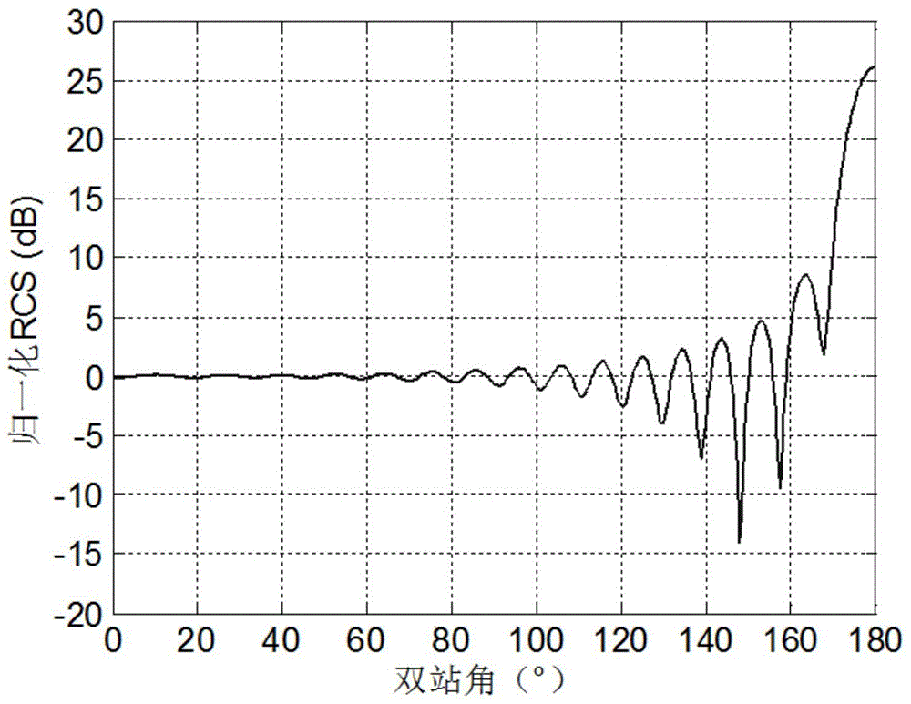
[0016] Defect of existing technology-1: Bradley et al. only studied the calibration characteristics of some traditional calibration bodies and their applicability in bi-station measurement calibration, but did not solve the problem of calibration body with the increase of bi-station angle The bistatic scattering of the bistatic scatter fluctuates with the bistatic angle, causing large calibration errors.
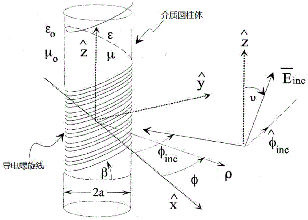
[0019] Defects of the prior art-2: the main technical defects that cause this calibrator design to be practically put into practice so far include three aspects: (1) due to the need to wind the metal conductive wire in strict accordance with a certain inclination angle On the medium cylinder, it is difficult to process and manufacture the entity; (2) there are certain difficulties in the accurate calculation of the theoretical scattering value of this calibration device; (3) it is difficult to analyze how the processing error affects the calibration accuracy
[0023] The main defect of prior art-3: (1) common two-station RCS measurement only needs a transmitter and a receiver, be placed in the required position (such as figure 1 shown), while using this calibration technique, it is necessary to use two RCS measurement radars (including transmitter and receiver) with basically the same performance, resulting in a multiplied increase in system cost; (2) due to the need to The calibration function can only be derived from two single-station measurements and two double-station measurements, which increases the factors affecting the calibration error. Compared with the calibration method using a single transmitter and receiver, the RCS calibration uncertainty is increased. Spend
[0051] (1) The receive polarization and transmit polarization of the PARC antenna are always orthogonal to each other, and the polarization of the transmit and receive antennas cannot be combined arbitrarily, which greatly reduces the form of its theoretical polarization scattering matrix, and many special forms of polarization scattering The matrix cannot be obtained by this single-antenna PARC, such as the identity matrix, which limits its application range;
[0052] (2) Since the solution is to measure the PARC of several antenna rotation angles to obtain the measured data, when there is a small rotation angle error in the measurement, it will affect the calibration accuracy;
[0053] (3) The robustness of the polarization calibration parameter extraction algorithm using this PARC is poor: once there is an abnormal value or a large error in the system measurement value at a certain moment during the calibration process, the accuracy of the extracted calibration parameters will be greatly reduced;
[0054] (4) Since a pair of orthogonally polarized feed sources work at the same time, it is impossible to use a polarization filter device to improve the polarization isolation of the antenna, which greatly affects the polarization calibration accuracy
[0062] (1) The technical design is very complex
This kind of digital PARC has very high requirements on the sampling rate of A / D and D / A. The timing logic of the digital radio frequency memory circuit is complex, and the writing and reading of signals and delay processing and other operations need to be controlled by clocks. In the running circuit, it is easy to have competition and risk, so that the whole system cannot work stably and normally;
[0063] (2) The calibration parameter solution process and algorithm are complex;
[0064] (3) The cost is high, the reliability and stability need to be verified, and there are no real products and practical application reports.
[0065] Defect of prior art-4: The two PARC devices designed with the above-mentioned single antenna or dual antenna are both single-station polarization calibration PARC devices, and cannot be used for dual-station measurement RCS calibration and dual-station measurement polarization calibration, so there is no Solve the problem of RCS calibration and polarization calibration in dual-station measurement

Method used


Image

  • A Calibration and Polarization Calibration Device and Measurement Calibration Method Used for Bistatic Radar Cross Section Measurement of Targets
  • A Calibration and Polarization Calibration Device and Measurement Calibration Method Used for Bistatic Radar Cross Section Measurement of Targets
  • A Calibration and Polarization Calibration Device and Measurement Calibration Method Used for Bistatic Radar Cross Section Measurement of Targets

Examples


Embodiment Construction

[0125] The present invention will be further described below in conjunction with the accompanying drawings and specific embodiments.

[0126] A schematic diagram of the overall structure of a calibration and polarization calibration device that can be used for target bistatic radar cross-section measurement and polarization calibration proposed by the present invention is as follows Figure 9 shown.

[0127] Figure 9 Among them, the dual-station scatterometry RCS calibration and polarization calibration device consists of a receiving antenna, a transmitting antenna, two azimuth-line-of-sight dual-axis rotation units, an azimuth rotation drive and controller, a pitch rotation drive and controller, a radio frequency combination, and a power supply combination , related matching installation interface and remote control interface and other functional modules. in:

[0128] Receiving and transmitting antenna: the receiving antenna is used to receive the radiation signal of the ...


PUM


Abstract

The invention discloses a measurement calibration and polarimetric calibration device (BPARC) for a target bistatic radar cross section (RCS) and a measurement calibration method thereof. The device is a double-antenna active polarization radar calibration (PARC) device with a biaxial rotation control mechanism, can simultaneously solve the problems of target bistatic RCS calibration and target bistatic polarization scattering matrix measurement calibration under the bistatic scattering measurement condition. As the bistatic RCS measurement calibration device, the BPARC can overcome the defects of the existing technology and device and ensures the stability of an RCS calibration value under different bistatic angles. As the polarimetric calibration device for bistatic polarization scattering matrix measurement, the BPARC retains all advantages of the existing single-station polarimetric calibration PARC device and also can be used for bistatic polarimetric calibration. The functions of bistatic RCS calibration and bistatic polarimetric calibration of the traditional PARC are increased.

Description

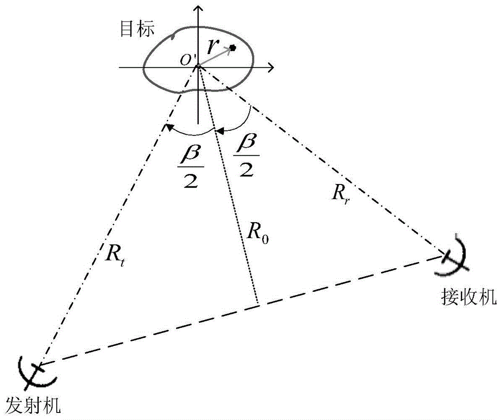
technical field [0001] The present invention relates to the technical field of radar cross section (RCS) measurement and processing of targets, in particular to a calibration and polarization calibration device (abbreviated as BPARC) and its measurement which can be used for target bistatic radar cross section (RCS) measurement Calibration method. Background technique [0002] The schematic diagram of the geometric relationship of the bistatic radar cross section (RCS) measurement is as follows: figure 1 shown. The bistatic radar equation can be expressed as: [0003] P r = P t G t G r λ 2 ( 4 π ) 3 R t ...

Claims


Application Information

Patent Timeline
Patent Type & Authority Patents(China)
IPC IPC(8): G01S7/40G01S7/03
CPCG01S7/40
Inventor 许小剑唐建国
Owner BEIHANG UNIV
Learn More