Down-hole vibration source

A wellbore and equipment technology, applied in the field of seismic analysis, can solve problems such as damage and impractical detonation of explosives

Inactive Publication Date: 2012-12-12
PRAD RES & DEV LTD
View PDF5 Cites 0 Cited by
  • Summary
  • Abstract
  • Description
  • Claims
  • Application Information

AI Technical Summary

Problems solved by technology

In other words, it is impractical to subsequently detonate the explosive because the charge could damage or ignite any nearby powder that would be used in the subsequent ignition

Method used


Image

  • Down-hole vibration source
  • Down-hole vibration source
  • Down-hole vibration source

Examples


Embodiment Construction

[0011] figure 1 A schematic diagram illustrating the downhole seismic source used to facilitate data collection. The seismic source is used in the borehole (100) and used to generate elastic dynamic waves (102) that can be measured by sensors (104a-104c). Specifically, P, S, SH, and SV type waves can be generated. The sensor may be located within the wellbore itself (e.g., sensor (104a)), in a nearby wellbore (105) (e.g., sensor (104c)), and in a formation close to the wellbore (e.g., sensor (104b)) . Based on the measurements obtained by the sensors, it is possible to detect, for example, the presence of fractures, stresses, and settlement interfaces in the formation. Detection of this state can be used to enhance oil and gas production.

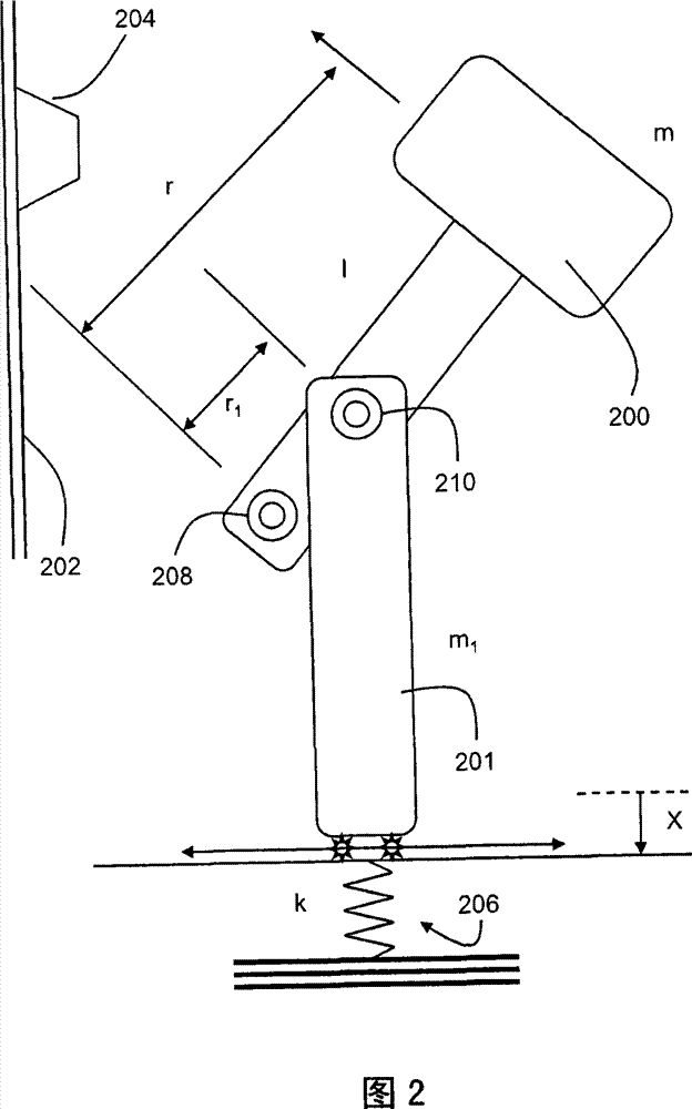
[0012] The seismic source includes an energy source component (106), an energy storage component (108), and a force converter and amplifying component (110). The energy source component (106) can be located above the ground or below the gr...


PUM


Abstract

Elastic dynamic wave is generated through a tool, wherein the tool comprises a hammer which is rotatablely connected with a shell by a first hinge and an actuator arm which is rotatablely connected with the hammer by a second hinge. The axial force applied to the actuator arm through a drive shaft and a spring is converted and amplified to radial impact force by the rotation of the hammer around the first hinge. The tool can further comprise a stabilizer arm connected to the actuator arm and the shell respectively by a third hinge and a fourth hinge. The shell can be an acoustical cable tool cylinder which is provided with an opening allowing the hammer body to extend outside the shell when rotating in a first direction. The shell can further comprise a second opening and a third opening,wherein the second opening allows the hammer body to extend outside the shell when rotating in a second direction and the third opening allows the hammer body to extend outside the shell when rotating between the first opening and the second opening.

Description

Technical field [0001] The present invention relates generally to underground wellbore technology, and more specifically, to a seismic analysis of the formation closest to the wellbore. Background technique [0002] Seismic analysis of stratum is a mature technology. The elastic dynamic wave generated by the seismic source at a known location is measured with a sensor array. Based on this measurement, it is possible to detect, for example, the presence of fractures, stresses, and settlement interfaces in the formation. Preferably, because it is sometimes necessary to obtain the measurement at a remote sensor, the seismic source should be relatively powerful, and the elastic dynamic wave at a specific frequency decays rapidly in the underground environment. Elastic dynamic waves of higher frequencies generally decay faster than elastic dynamic waves of lower frequencies. Because different types of elastic dynamic waves and elastic dynamic waves of different frequencies are used...

Claims


Application Information

Patent Timeline
Patent Type & Authority Patents(China)
IPC IPC(8): G01V1/143
Inventor 章中理查德·T·科茨琼·圣日耳曼
Owner PRAD RES & DEV LTD
Why Eureka
Try Eureka