


Quick Research
Generate reliable direction feasibility study reports for your R&D in just a few steps.

Technical Q&A
Discover and master advanced knowledge NOW. Basics, ideas, possibilities, all at once.

Find Solutions
As an expert in R&D theories, this can generate solutions to your technical problems instantly.

Evaluate Feasibility
Analyze your overall solution with one click, know your potential R&D risks in advance.

Monitor Landscape
Get weekly tech updates, stay abreast of the latest tech innovations and key insights.
Transmitter apparatus, receiver apparatus, communication apparatus and communication system
A technology of a transmitting device and a communication system, applied in the field of communication systems, can solve the problems of transmission rate control, inability to use limited frequency bands more effectively, and inability to allocate more transmission information, etc., and achieve the effect of improving transmission quality
- Summary
- Abstract
- Description
- Claims
- Application Information
AI Technical Summary
Problems solved by technology
Method used
Image


Examples
Embodiment approach 1
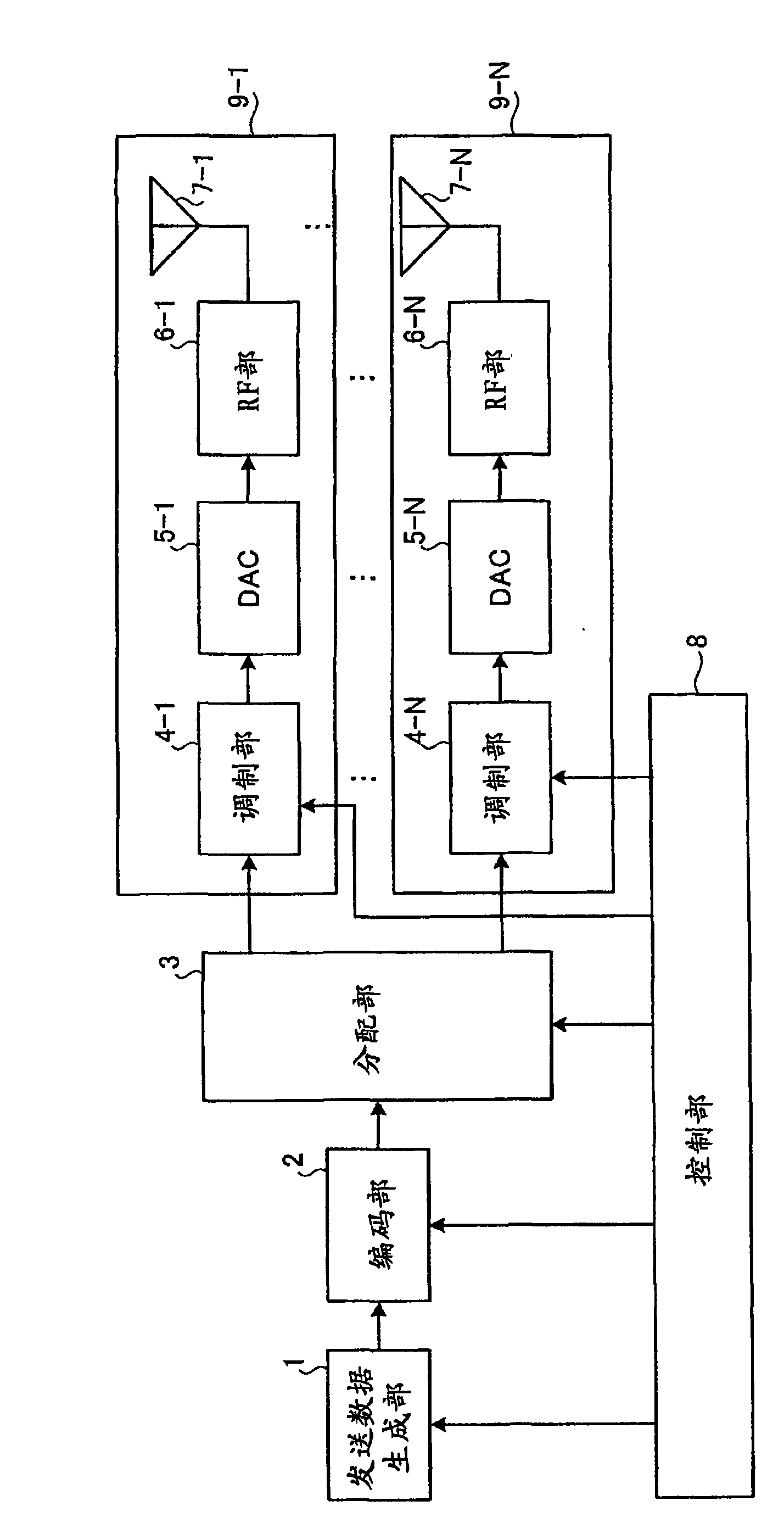
[0052] Picture 1-1 It is a diagram showing an example of the functional configuration of Embodiment 1 of the transmission device of the present invention. Figure 1-2 It is a diagram showing another example of the functional configuration of Embodiment 1 of the transmission device of the present invention. Such as Picture 1-1 , Figure 1-2 As shown, the transmission device of this embodiment is composed of a transmission data generation unit 1, an encoding unit 2, a distribution unit 3, modulation units 4-1 to 4-N (N: the number of transmission antennas), a DAC (Digital Analog Converter, digital Analog converters) 5-1 to 5-N, RF sections 6-1 to 6-N, transmitting antennas 7-1 to 7-N, and a control section 8 are configured. In addition, a part composed of the modulation unit 4, the DAC 5, the RF unit 6, and the transmission antenna 7 having the same branch number is referred to as one transmission branch 9-1 to 9-N. In this embodiment, one transmission branch corresponds to ...
Embodiment approach 2
[0083] Figure 5 It is a diagram showing an example of the functional configuration of Embodiment 2 of the transmission device of the present invention. In the transmission device of this embodiment, instead of the Picture 1-1 The control unit 8 of the structural example is provided with a control unit 8a. Other configurations are the same as those of Embodiment 1. For the part having the same function as Embodiment 1, add and Picture 1-1 The same symbols are used and explanations are omitted.
[0084] In this embodiment, a transmission priority is set for each transmission data block, and transmission data is allocated to the transmission branches 9-1 to 9-N according to the priority. Figure 6 An example of a method of allocating error correction coded transmission data blocks in this embodiment is shown. Figure 6 This is an example where N=3 and DN=2. exist Figure 6 Among them, the transmission data blocks 16 - 1 and 16 - 2 are transmission data blocks that have un...
Embodiment approach 3
[0101] Figure 8 It is a diagram showing an example of the functional configuration of Embodiment 3 of the transmission device of the present invention. In the transmission device of this embodiment, for Embodiment 1 Picture 1-1 The example of the functional configuration of FIG. 10 adds interleavers 21 - 1 to 21 -N for interleaving, and includes a control unit 8 b instead of the control unit 8 of the first embodiment. The control unit 8b adds a function of instructing the interleavers 21-1 to 21-N on the interleaving processing method to the functions of the control unit 8 according to the first embodiment. Other configurations are the same as those of Embodiment 1. For the part having the same function as Embodiment 1, add and Picture 1-1 The same symbols are used and explanations are omitted.
[0102] Next, the operation of the transmission device according to this embodiment will be described. The operation of this embodiment is the same as that of Embodiment 1 or Emb...
PUM
 Abstract
Description
Claims
Application Information
 - R&D Engineer
- R&D Manager
- IP Professional
- Industry Leading Data Capabilities
- Powerful AI technology
- Patent DNA Extraction
Browse by: Latest US Patents, China's latest patents, Technical Efficacy Thesaurus, Application Domain, Technology Topic, Popular Technical Reports.
© 2024 PatSnap. All rights reserved.Legal|Privacy policy|Modern Slavery Act Transparency Statement|Sitemap|About US| Contact US: help@patsnap.com