Discharge lamp lighting circuit
A discharge lamp and circuit technology, which is applied in the direction of electric light sources, electrical components, lighting devices, etc., can solve the problems of high temperature, high heat generation of switching elements and rectifier diodes, and the inability to fully popularize discharge lamps for automobiles. Effects of heat reduction and cost reduction
- Summary
- Abstract
- Description
- Claims
- Application Information
AI Technical Summary
Problems solved by technology
Method used
Image

Examples
no. 1 Embodiment approach
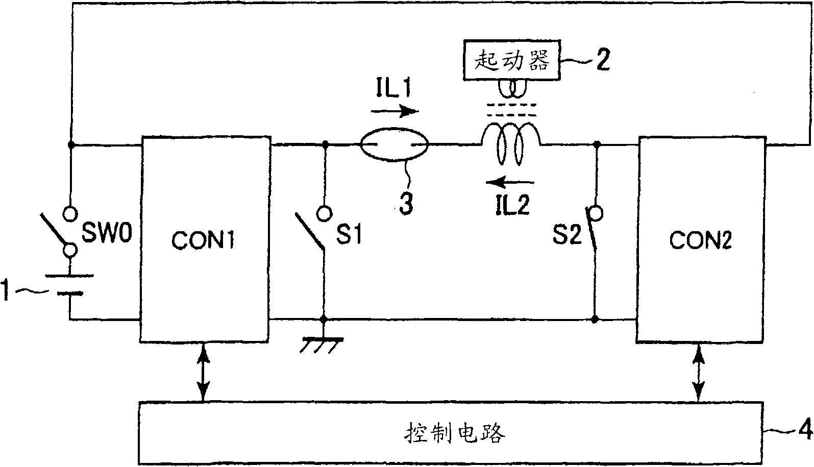
[0047] figure 1 A conceptual diagram of the discharge lamp lighting circuit according to the first embodiment of the present invention is shown in the following description.
[0048] as it should figure 1 As shown, the discharge lamp lighting circuit is used in automobiles, for example, and is especially suitable for headlights and the like. It adopts low-frequency AC lighting method, including power source 1 such as battery, switch SW0, first and second converters CON1 and CON2 of the dual system, switching elements S1 and S2, starter circuit 2, and discharge lamp 3. The first and second converters CON1 and CON2 are buck-boost converters that not only step up but also step down, and the output terminals constituting the output of the converters are electrically connected to the electrodes of the discharge lamp 3 , respectively.
[0049] In such a configuration, when the discharge lamp 3 in which the switch SW0 is turned on is turned on, the control circuit 4 operates the fi...
no. 2 Embodiment approach
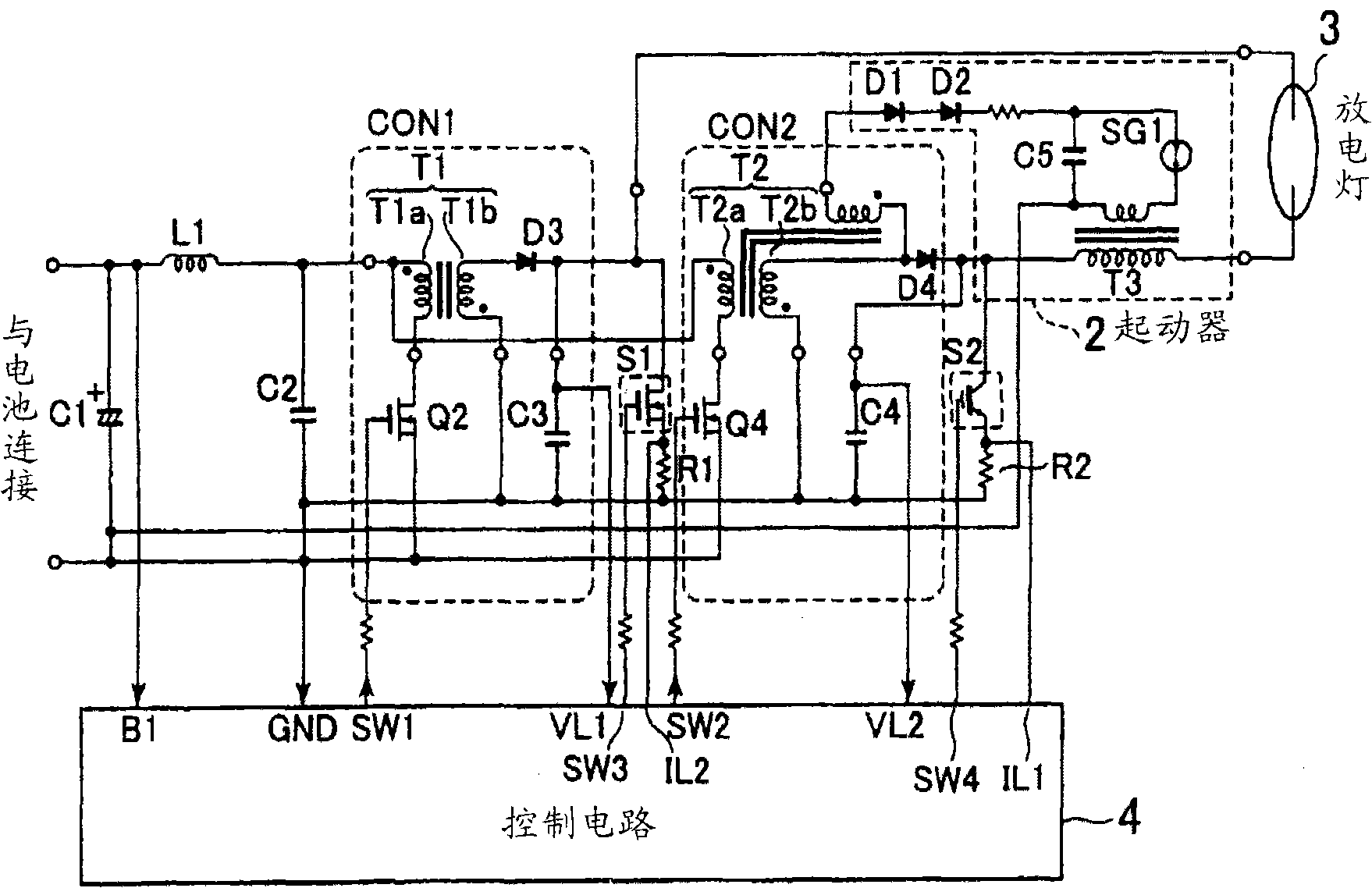
[0059] figure 2 The structure of the discharge lamp lighting circuit which concerns on 2nd Embodiment of this invention is shown in the following, and it demonstrates.
[0060] as it should figure 2 As shown, the discharge lamp lighting circuit mainly includes first and second converters CON1 and CON2 , a starter circuit 2 , a discharge lamp 3 , and a control circuit 4 .
[0061] A power supply voltage supplied from an unillustrated power supply is supplied to the primary side (primary side coil T1a) of the transformer T1 of the first converter CON1 via the inductor L1. The capacitor C1 has one end connected to the power supply side terminal of the inductor L1 and the other end connected to the ground. The winding starting points of the respective coils T1a, T1b of the transformer T1 are indicated by black circles in the figure. In the first converter CON1, the switching element Q2 is connected to the winding terminal terminal of the primary winding T1a of the transformer...
no. 3 Embodiment approach
[0075] Figure 4 The structure of the discharge lamp lighting circuit which concerns on 3rd Embodiment of this invention is shown and demonstrated in hereinafter.
[0076] Here, for figure 2 The same reference numerals are attached to the same structures, and repeated explanations are omitted.
[0077] In the aforementioned second embodiment ( figure 2 ), switching elements S1 and S2 are arranged at the output ends of the first and second converters CON1 and CON2, but these elements are omitted in the third embodiment. In addition, rectifier diodes D3 and D4 are provided for the first and second converters CON1 and CON2 , but this structure is also omitted.
[0078] That is, in the first converter CON1, the switching element Q3 is provided at the winding start terminal on the secondary side of the transformer T1. In this example, an N-channel MOSFET is used as the switching element Q3. The drain of the switching element Q3 is connected to the winding start terminal of t...
PUM
 Abstract
Description
Claims
Application Information
 - Generate Ideas
- Intellectual Property
- Life Sciences
- Materials
- Tech Scout
- Unparalleled Data Quality
- Higher Quality Content
- 60% Fewer Hallucinations
Browse by: Latest US Patents, China's latest patents, Technical Efficacy Thesaurus, Application Domain, Technology Topic, Popular Technical Reports.
© 2025 PatSnap. All rights reserved.Legal|Privacy policy|Modern Slavery Act Transparency Statement|Sitemap|About US| Contact US: help@patsnap.com