High-power factor correcting circuit
A high power factor, correction circuit technology, applied in the field of power supply, can solve problems such as increasing circuit loss and increasing cost
- Summary
- Abstract
- Description
- Claims
- Application Information
AI Technical Summary
Problems solved by technology
Method used
Image

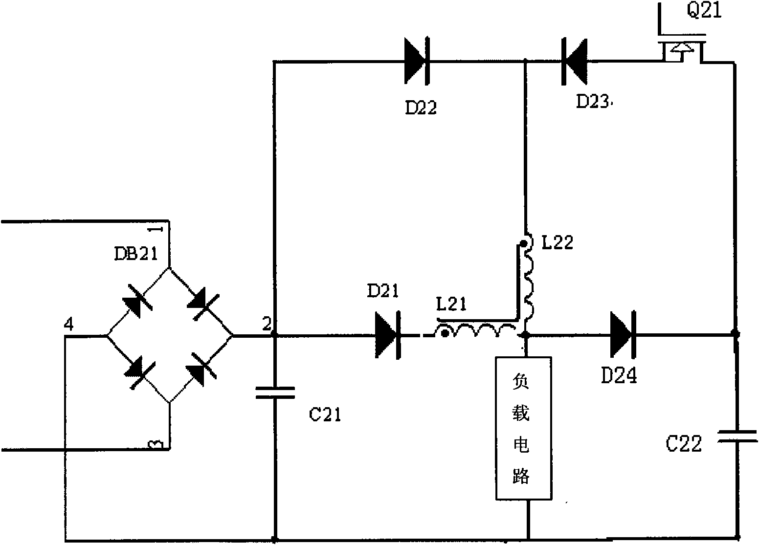
Examples
specific Embodiment approach 1
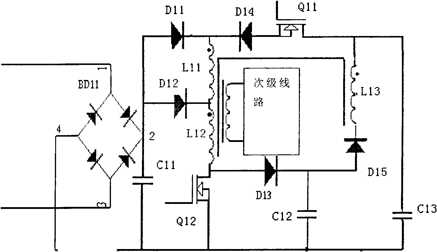
[0016] For specific implementation plan one, please refer to figure 1
[0017] The specific PFC switching power supply circuit of the first scheme of the present invention includes a rectifier bridge and a switching transformer, wherein the switching transformer has three groups of primary coils, the first primary coil L11, the second group of primary coils L12, the third group of primary coils L13 and a A set of secondary coils, two field effect transistors, main field effect transistor Q12 and auxiliary field effect transistor Q11, three capacitors; filter capacitor C11, energy storage capacitor C13, and clamping capacitor C12. Five diodes, the first freewheeling diode D11, the second freewheeling diode D12, the first reverse isolation diode D13, the second reverse isolation diode D14, and the third reverse isolation diode D15. Wherein the input terminal of the rectifier bridge is connected to alternating current, the filter capacitor C11 is connected to the output terminal...
PUM
 Abstract
Description
Claims
Application Information
 - Generate Ideas
- Intellectual Property
- Life Sciences
- Materials
- Tech Scout
- Unparalleled Data Quality
- Higher Quality Content
- 60% Fewer Hallucinations
Browse by: Latest US Patents, China's latest patents, Technical Efficacy Thesaurus, Application Domain, Technology Topic, Popular Technical Reports.
© 2025 PatSnap. All rights reserved.Legal|Privacy policy|Modern Slavery Act Transparency Statement|Sitemap|About US| Contact US: help@patsnap.com