
Battery pack

A technology for battery packs and battery packs, which is applied to battery pack components, secondary batteries, circuits, etc., and can solve the problems of increasing circuit substrates, temperature rise, and inability to configure components affected by heat.

Active Publication Date: 2009-09-09
SANYO ELECTRIC CO LTD
View PDF2 Cites 43 Cited by
  • Summary
  • Abstract
  • Description
  • Claims
  • Application Information

AI Technical Summary

Problems solved by technology

In addition, since the temperature rises due to heat generation, parts affected by heat cannot be placed nearby.
Therefore, it is necessary to provide a space for heat dissipation around the current detection resistor, resulting in a further increase in the size of the circuit board.

Method used


Image

  • Battery pack
  • Battery pack
  • Battery pack

Examples


Embodiment Construction

[0131] Hereinafter, embodiments of the present invention will be described with reference to the drawings. However, the embodiments shown below are examples illustrating a storage battery pack for embodying the technical idea of ​​the present invention, and the present invention does not limit the storage battery pack to the following embodiments.

[0132] In addition, in this specification, in order to understand the content of a claim easily, the code|symbol corresponding to the member shown in an Example is in a claim and summary of invention. However, the components shown in the claims are by no means limited to those of the embodiment.

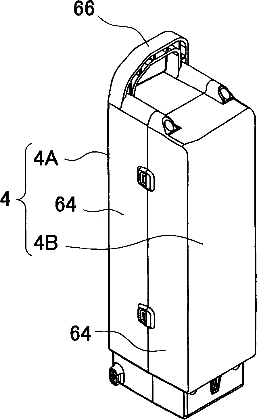
[0133] figure 1 and figure 2 In the shown battery pack, batteries 1 are accommodated in an exterior case 4 as a battery block 10 . Figure 3 ~ Figure 5A bottom perspective view, a cross-sectional perspective view, and an exploded perspective view of the battery block 10 are respectively shown. In the storage battery packs in these fi...


PUM


Abstract

The present invention relates to a battery pack capable of reducing the size of a circuit substrate making the parts influenced by heating away from the current detecting resistor. A battery pack includes a battery block 10 including plural batteries 1 accommodated in a battery accommodating portion 15 of a battery holder 2, and a current detecting resistor 40 detecting the currents of the batteries 1. The holder 2 includes a pair of support side walls 12 arranged on both sides of the accommodating portion 15. The pair of side walls 12 have electrode windows 19 opening to connect lead plates 5 to end electrodes of the batteries 1 that are accommodated in the accommodating portion 15. The lead plates 5 are arranged on the exterior sides of the side walls 12. The side walls 12 are formed wider than the accommodating portion 15 to form protruding portions 16 protruding externally from the accommodating portion 15. The current detecting resistor 40 is arranged on the interior sides of theprotruding portions 16 of the pair of side walls 12.

Description

technical field [0001] The invention relates to a storage battery pack mainly suitable for discharging large currents such as electric bicycles. Background technique [0002] The battery pack detects the current flowing in the battery, and can control the state of charging and discharging according to the detected current to prolong the service life of the battery. For example, detect the current of the battery to limit the maximum current, or detect over-current to cut off the current, or, accumulate the current of charge and discharge, calculate the residual capacity, and prevent over-charging or over-discharging according to the residual capacity, so as to protect the battery at the same time Perform charge and discharge. The storage battery pack realizing this is provided with a current detection resistor for detecting the current of the battery. The charging current and discharging current of the battery are detected according to the voltage sensed at both ends of the...

Claims


Application Information

Patent Timeline
IPC IPC(8): H01M10/48H01M2/10H01M2/34H05K1/18H01M50/209H01M50/227
CPCY02E60/12H01M10/482H01M2/105H01M2/1094H01M10/0525H01M10/486H01M10/425H01M10/488H01M2/1077Y02E60/10H01M50/213H01M50/24H01M50/227H01M50/209
Inventor 山上定男大野尉浩衣川辉将
Owner SANYO ELECTRIC CO LTD
Learn More