
Lamp tube device with electric connecting sleeve of winding body and light source module

A light source module and electrical connection technology, which is applied to the parts of gas discharge lamps, lighting devices, light source fixing, etc. Effect

Active Publication Date: 2009-09-09
AU OPTRONICS CORP
View PDF0 Cites 4 Cited by
  • Summary
  • Abstract
  • Description
  • Claims
  • Application Information

AI Technical Summary

Problems solved by technology

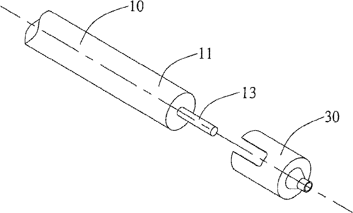
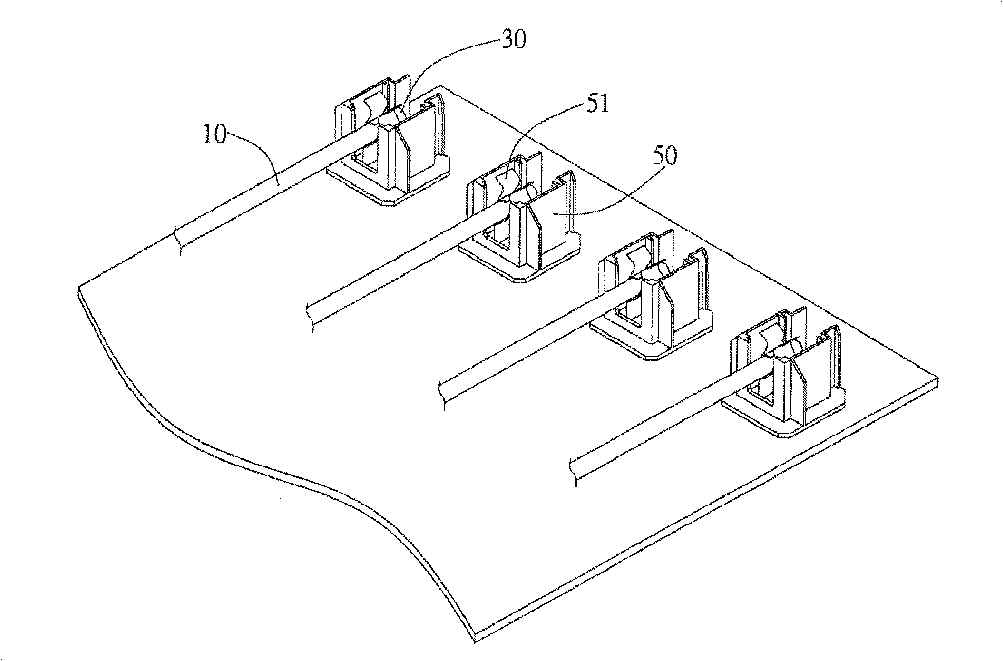
In addition, since the metal cap 30 is clamped by the spring socket 51, and the metal cap 30 tightly covers the end 11 of the lamp tube 10, the end of the lamp tube 10 will Part 11 and shrapnel socket 51 cannot move relative to each other in the axial and radial directions
Therefore, when the external force impacts the backlight module, the following two results will usually be caused: 1. The shrapnel socket 51 transmits the radial and axial external force to the metal cap 30, and the metal cap 30 transmits all the external force to the end of the lamp tube 10. 11, causing damage to the lamp tube 10; 2. The shrapnel socket 51 cannot hold the end 11 of the lamp tube 10, causing the lamp tube 10 to jump off from the shrapnel socket 51, resulting in interruption of electrical connection

Method used


Image

  • Lamp tube device with electric connecting sleeve of winding body and light source module
  • Lamp tube device with electric connecting sleeve of winding body and light source module
  • Lamp tube device with electric connecting sleeve of winding body and light source module

Examples


Embodiment Construction

[0052] The invention provides a lamp device and a light source module using the lamp device. In a preferred embodiment, the lamp device and the light source module of the present invention are applied in a backlight module to provide the light source required by the backlight module. However, in different embodiments, the lamp device and the light source module can also be used in other electronic devices as the required light source. In addition, the backlight module using the lamp device and the light source module of the present invention can be applied in liquid crystal displays to provide the light required by the liquid crystal panel.

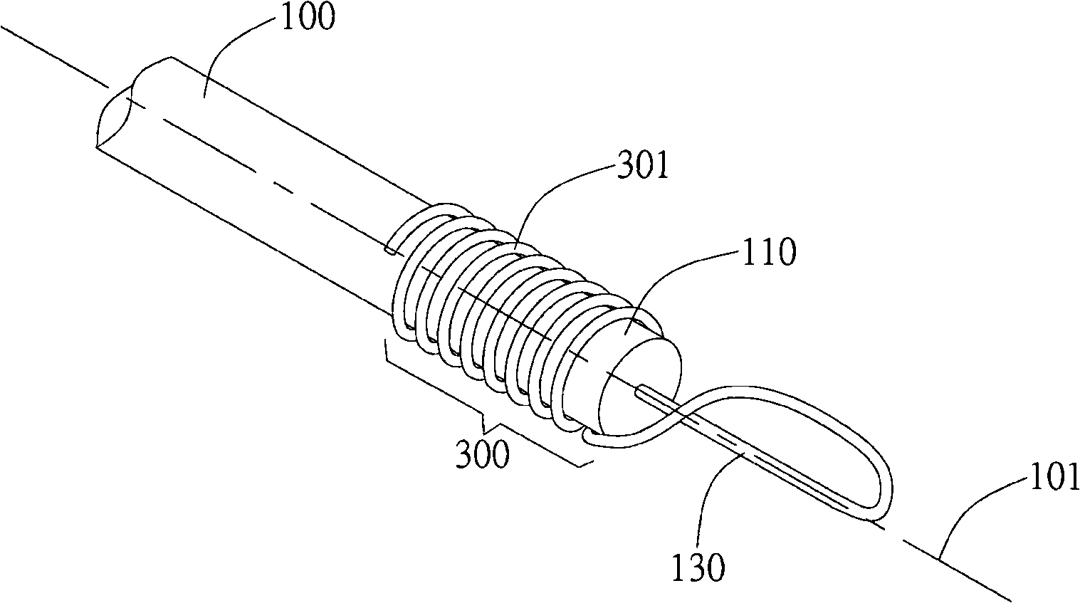
[0053] Such as Figure 2a As shown, the lamp device of the present invention includes a lamp body 100 and an electrical connection sleeve 300 of the wound body. The lamp body 100 preferably comprises a cold cathode lamp (CCFL) or other types of lamps. The winding body electrical connection sleeve 300 is preferably wound with a metal wi...


PUM


Abstract

The invention relates to a lamp tube device with an electric connecting sleeve of a winding body and a light source module. The lamp tube device comprises a lamp tube body and the electric connecting sleeve of the winding body; wherein the lamp tube body has an end part and a guide wire extending outward from the end part. The position of the electric connecting sleeve of the winding body corresponds to the end part of the lamp tube body; the electric connecting sleeve of the winding body is electrically connected with the guide wire so as to transmit electric power into the lamp tube body from outside. The electric connecting sleeve of the winding body winds along the direction of an axle center of the lamp tube body and can carry out elastic or non-elastic stretching or compression along the direction of the axle center. Besides the lamp tube device, the light source module also comprises a lamp tube connecting seat which comprises a power end which is electrically connected with the electric connecting sleeve of the winding body to supply power so as to lead the lamp tube body to emit light. The lamp tube device and the light source module are easy to assemble, have better radiating effect, can reduce the damage of the lamp tube due to external force and can reduce the chance of tripping of the lamp tube from the connecting seat.

Description

technical field [0001] The invention relates to a lamp device and a light source module; specifically, the invention relates to a lamp device and a light source module used in a backlight module. Background technique [0002] Backlight modules are widely used in various products, such as liquid crystal displays, to provide light sources required by the products. In recent years, as the demand for liquid crystal displays increases, the technology of backlight modules is becoming more and more mature. As for the common backlight modules currently on the market, light tubes are still the main light source used in the backlight modules because of their low cost. [0003] In the traditional design, when assembling, the end of the lamp tube is first inserted into the connecting seat on the base plate, and then the guide wire protruding from the electrode of the lamp tube is connected to the terminal of the connecting seat by welding. From a production point of view, this design ...

Claims


Application Information

Patent Timeline
IPC IPC(8): H01J61/36F21V23/06F21V19/00G02F1/13357
Inventor 粘松木李彦霖傅世泽许轩豪
Owner AU OPTRONICS CORP
Learn More