
Developing device and process cartridge

一种显影装置、显影剂的技术,应用在显影剂、仪器、应用电荷图形的电记录工艺等方向

Inactive Publication Date: 2009-09-02
CANON KK
View PDF2 Cites 2 Cited by
  • Summary
  • Abstract
  • Description
  • Claims
  • Application Information

AI Technical Summary

Problems solved by technology

However, under normal circumstances, the maximum value of the electric field is almost set as the upper limit where no discharge occurs at the closest position between the photosensitive drum and the developing sleeve, so the value cannot be made higher.

Method used


Image

  • Developing device and process cartridge
  • Developing device and process cartridge
  • Developing device and process cartridge

Examples


manufacture example

[0146] (Manufacturing example and working example)

[0147] The present invention will be described more specifically below by referring to Production Examples and Examples. It should be noted that the parts of the following compounds represent parts by mass.

[0148] Manufacture of magnetic powder

[0149]

[0150] In an aqueous solution of ferrous sulfate, 1.0 to 1.1 equivalents of caustic soda solution relative to the iron element, 1.5% by mass of sodium hexametaphosphate when the phosphorus element is converted to the iron element, and 1.5% by mass when the silicon element is converted to the iron element 1.5% by mass of sodium silicate hydrate to prepare an aqueous solution containing ferrous hydroxide.

[0151] While maintaining the pH at 9, air was blown into the obtained aqueous solution, and oxidation was performed at 80 to 90° C. to prepare a seeded slurry.

[0152] In this slurry, an aqueous solution of ferrous sulfate is added so that the amount of alkali ini...

Embodiment 1

[0199] The cartridge (1) in Table 3 was used for the developing device for evaluation. A cartridge (1) was filled with the magnetic toner (1) of Table 2, and inserted into a laser beam printer-LBP-1210 (manufactured by Canon Inc.). A printing test of 1000 image output was performed at normal temperature and humidity (23° C., 60% RH). As an image for durability, an A letter (8 dots) image with a coverage rate of 4% was used. Use 75g / m 2 A4 size paper is used as the recording medium.

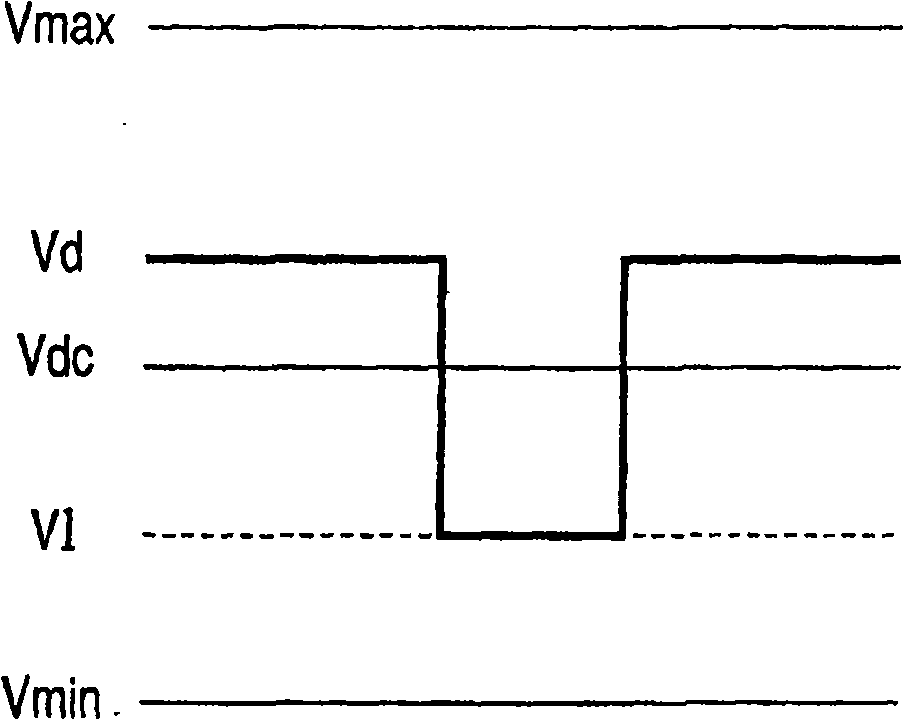
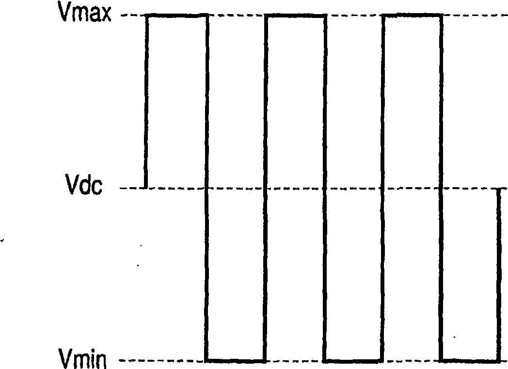
[0200] The latent image potential on the photosensitive drum 1 was set to be Vd = -600 (V) and V1 = -150 (V). The developing bias potential was set to Vpp=1600 (V). As provisional DC bias components, Vdc=-450(V) and (Vmax=-1250(V) and Vmin=+350(V)) are set. Before the printing test of 1000 image output, the Vdc value was adjusted so that the measured value of a 5 mm square black image printed in the center and four corners of the printing paper by a Macbeth reflection densitometer (manufactur...

Embodiment 2 and 3

[0215] As a developing device for evaluation, the cartridge (1) shown in Table 3 was used and filled with the magnetic toners (2) and (5) shown in Table 2 and a printing test was performed as in Example 1. Table 4 shows the results.


PUM


Abstract

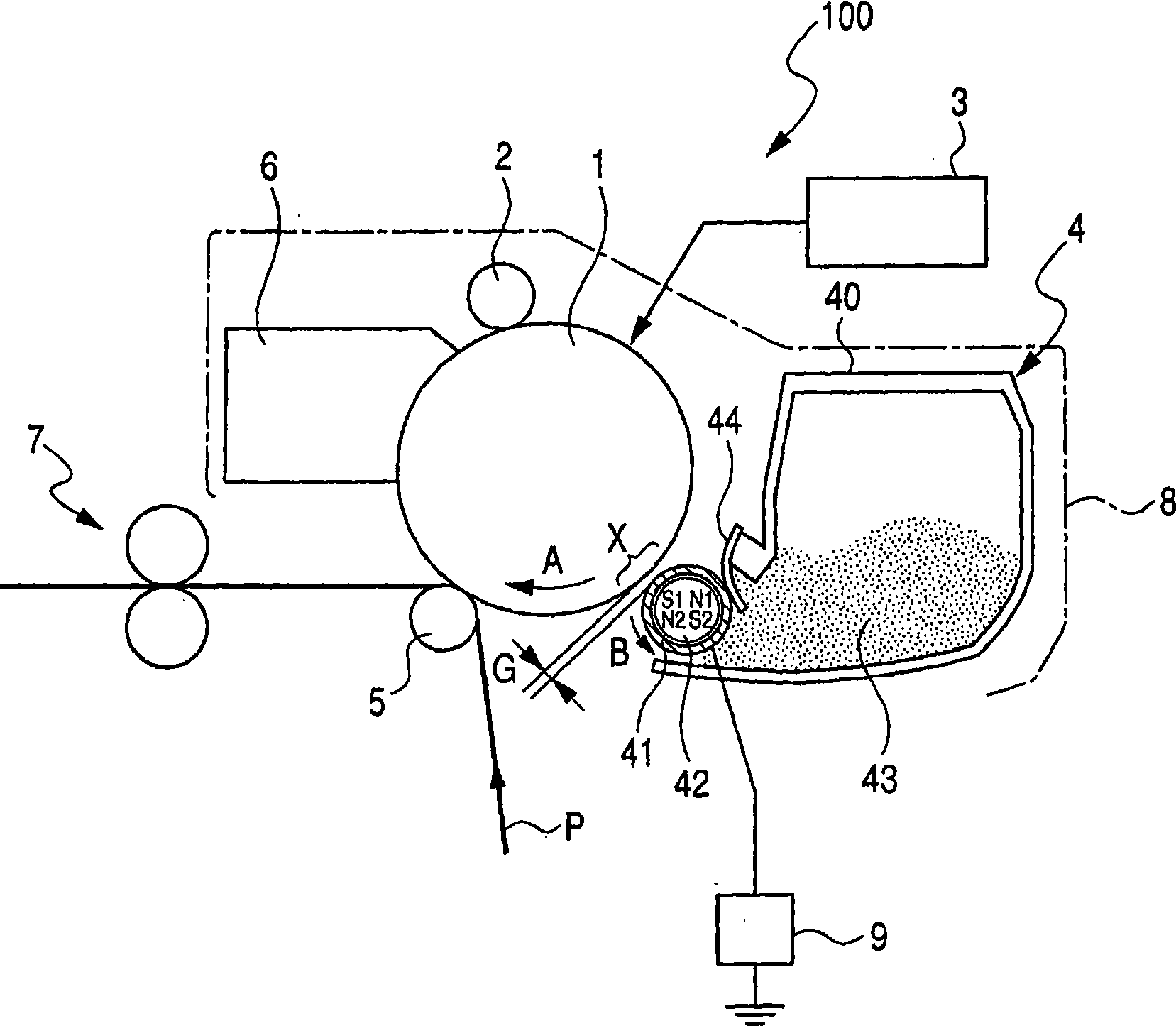
A developing apparatus, a process cartridge and an image forming apparatus of which the image density can be maintained and the fogged image and the uneven density can be within an acceptable level even when the diameter of a developer carrying member is not more than 12 mm. The outer diameter of the developer carrying member 41 is not less than 8 mm and not more than 12 mm, and a magnetic mono-component developer 43 has a saturation magnetization of not less than 20 Am / kg and not more than 37 Am / kg when the magnetic field of 79.6 kA / m (1000 oersteds) is applied, the magnetization of not less than 70% and not more than 80% of the saturation magnetization when the magnetic field is lowered to 55.7 kA / m (700 oersteds), and the magnetization of not less than 50% and not more than 62% of the saturation magnetization when the magnetic field is lowered to 39.8 kA / m (500 oersteds).

Description

technical field [0001] The present invention relates to a developing device and a process cartridge employing a non-contact developing system using a magnetic one-component developer for making an image formed on an image-carrying member by an electrophotographic printing method, an electrostatic recording method, or the like. Electrostatic latent image visualization. Background technique [0002] In recent years, for an image forming apparatus that forms an image by electrophotographic printing, electrostatic recording, etc., as a printer or copier for personal use, there has been an increasing demand for smaller size and higher speed. Furthermore, from the viewpoint of maintenance of such an apparatus, convenience is sought for a developing unit / cleaning unit including toner / waste toner detachably mountable on the apparatus main body. [0003] In order to achieve miniaturization, it is required to make an image carrying member, a developer carrying member, and the like us...

Claims


Application Information

Patent Timeline
Patent Type & Authority Applications(China)
IPC IPC(8): G03G15/08G03G9/083G03G15/09
CPCG03G2215/0614G03G15/0914G03G15/09G03G9/09733G03G9/08711G03G9/08755G03G2215/0619
Inventor 尾岛磨佐基加藤雅仁吉田延喜居波聪道上正
Owner CANON KK
Learn More