
Compressed air supply system and method for determining the parameters of said system

A technology for compressed air and equipment, applied in the arrangement of pumps/compressors, air handling units, transportation and packaging, etc., can solve problems such as parameterization

Active Publication Date: 2009-09-02
WABCO EURO BVBA SPRL
View PDF1 Cites 16 Cited by
  • Summary
  • Abstract
  • Description
  • Claims
  • Application Information

AI Technical Summary

Problems solved by technology

[0004] The known air preparation device has the disadvantage that the air preparation device either has to be calibrated mechanically by the manufacturer or has to be parameterized in terms of software

Method used


Image

  • Compressed air supply system and method for determining the parameters of said system
  • Compressed air supply system and method for determining the parameters of said system
  • Compressed air supply system and method for determining the parameters of said system

Examples


Embodiment Construction

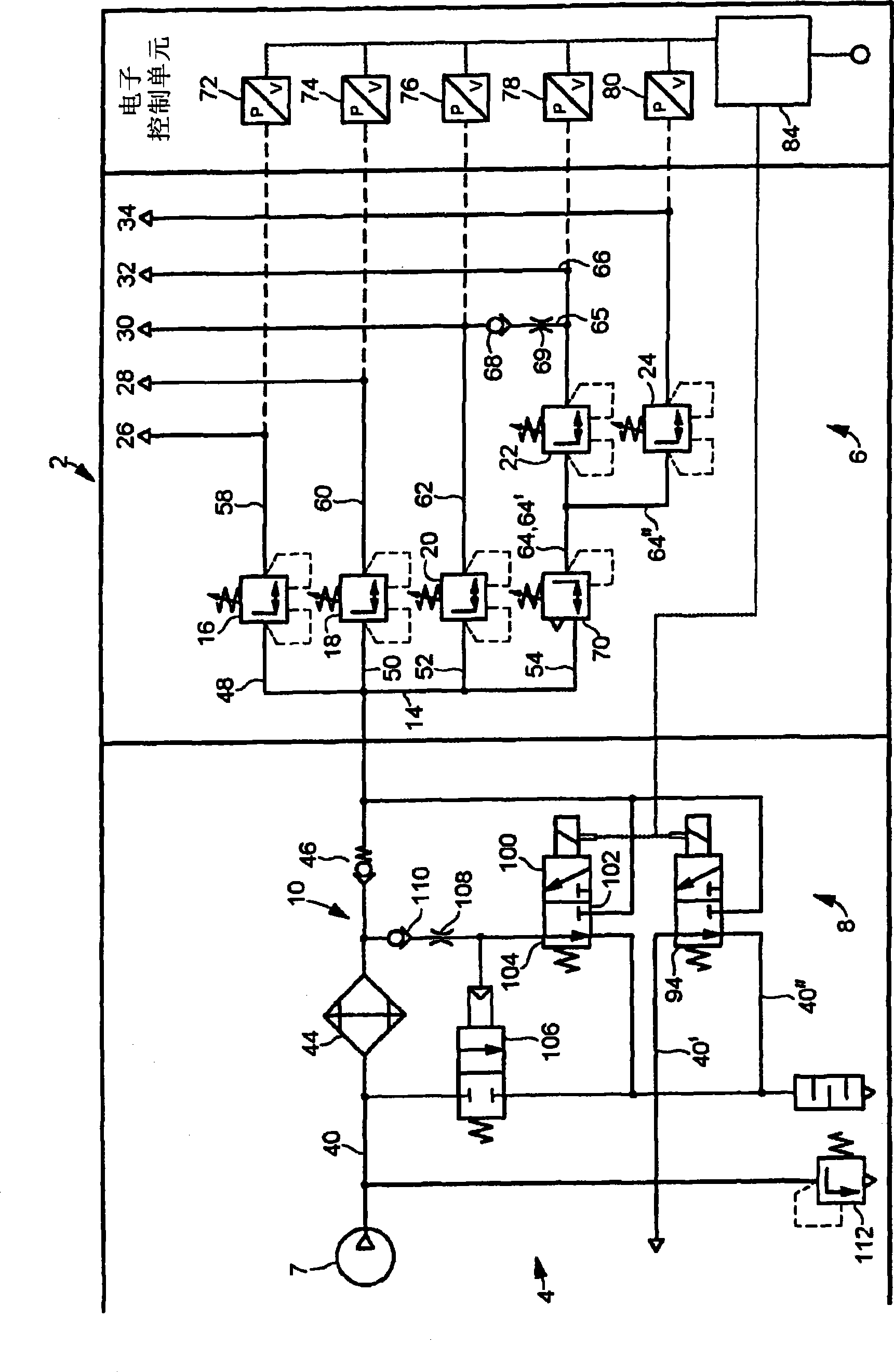
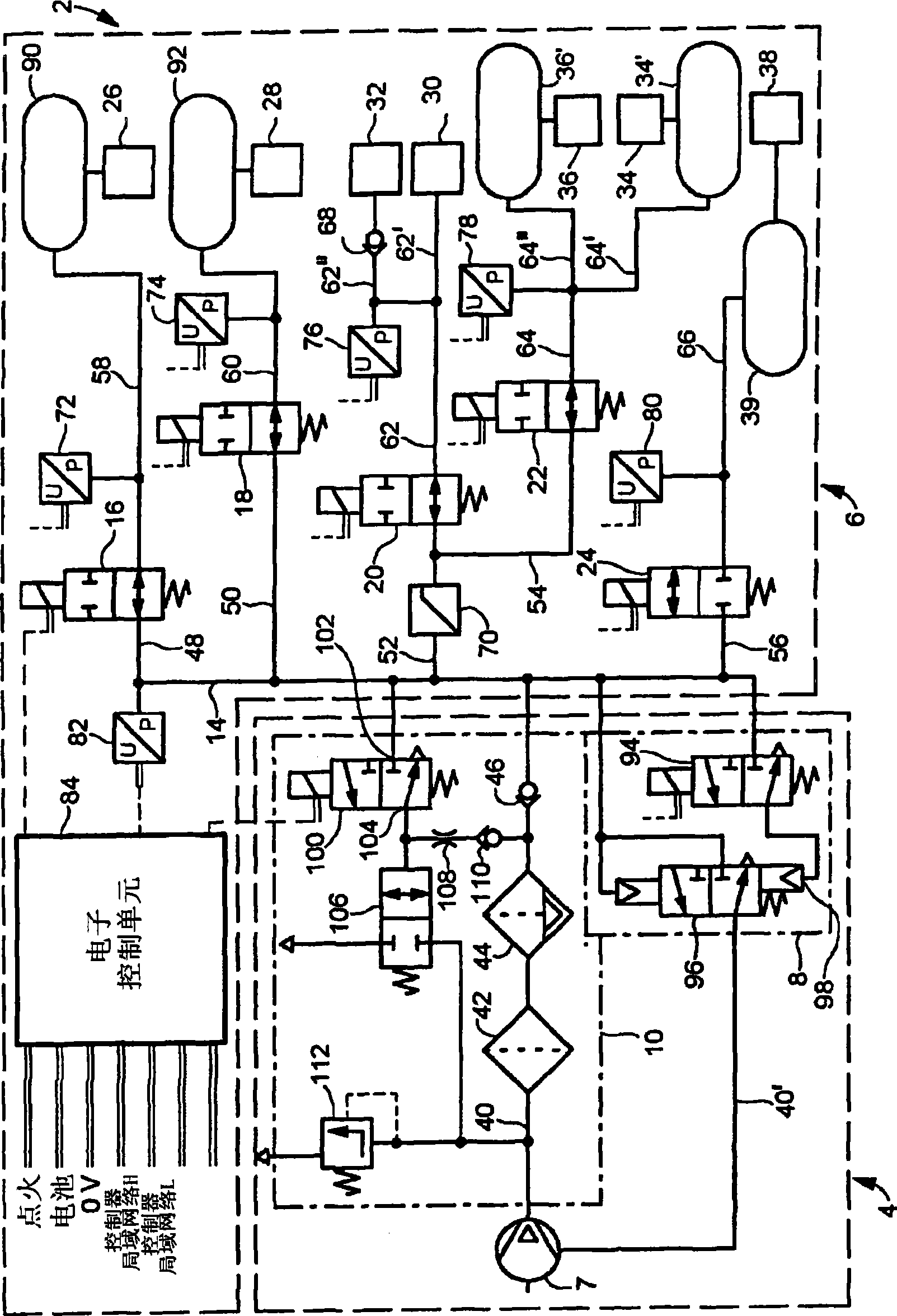
[0016] Attached is figure 1 shows a compressed air preparation device 2 with a compressed air supply 4 and a consumer part 6 . The compressed air supply section 4 includes a compressor 7 , a compressor control device 8 and an air dryer section 10 .

[0017] The consumer part 6 has a compressed air distribution line 14 branching off into a plurality of valves 16 , 18 , 20 , 22 , 24 and a plurality of consumer circuits 26 , 28 , 30 , 32 , 34 supplied with compressed air via the valves.

[0018] A compressed air supply line 40 leads from the compressor 7 via an air dryer scroll 44 (to which a filter (not shown) may be preceded) and a non-return valve 46 to the distribution line 14 , the lines 48 , 50 , 52 , 54 leading to the valves branch off from the distribution line 14 . Compressed air lines 58 , 60 , 62 , 64 lead from the valves to consumer circuits. Line 64 branches into lines 64 ′, 64 ″ leading to circuits 32 and 34 , wherein line 64 ′ branches into lines 65 , 66 leading...


PUM


Abstract

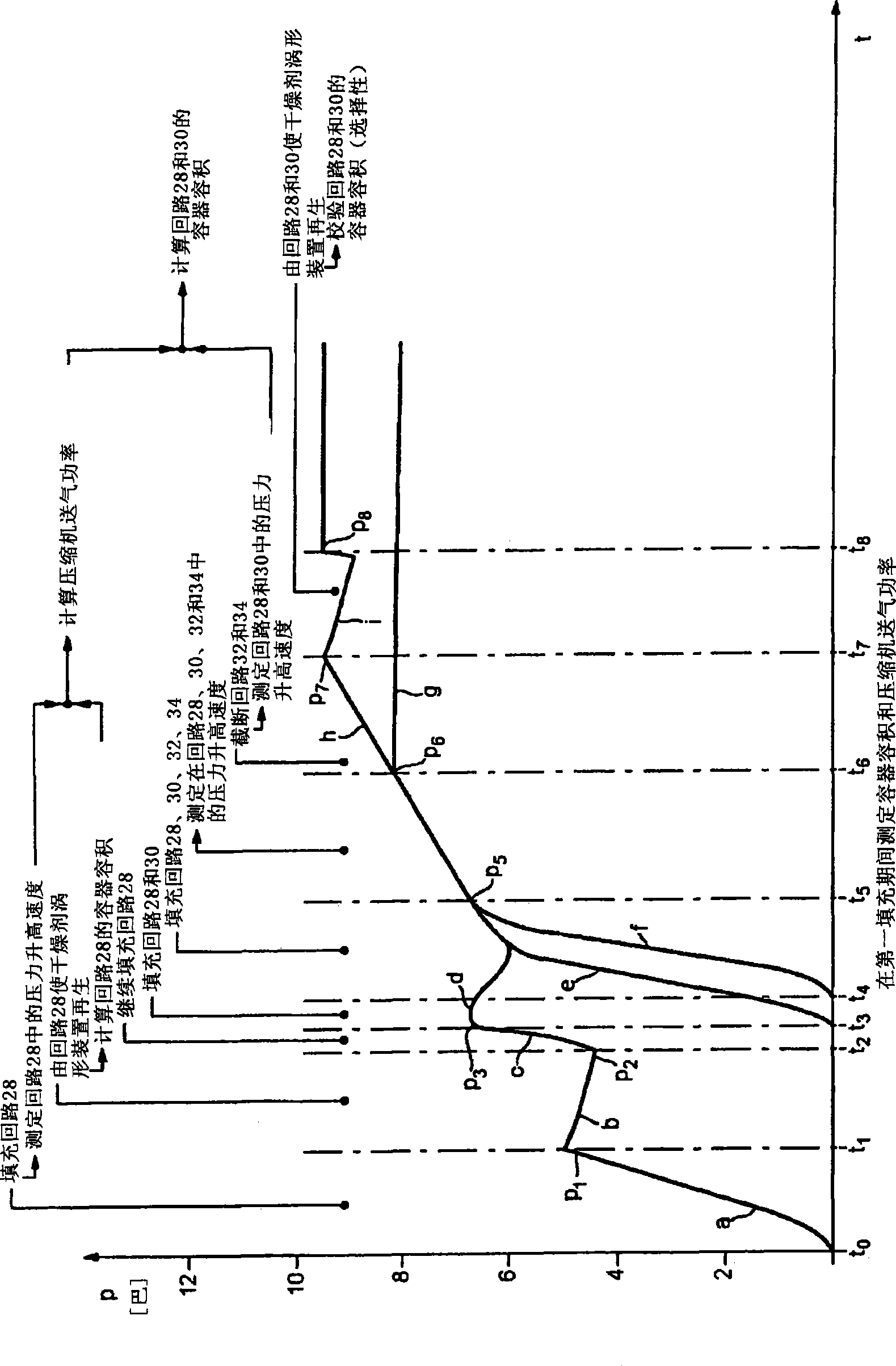
The invention relates to a compressed air supply system for motor vehicles comprising a compressed air supply part consisting of a compressor, an air drying part comprising an air dryer, a filter, a valve and a compressed air consumer part consisting of compressed air consumer circuits provided with operational brake circuits, which are supplied with compressed air via a multi-circuit safety valve. The operational brake circuits and optionally, at least one other compressed air consumer circuit comprises compressed air containers and the pressure in said compressed air consumer circuits is monitored by sensors, the electric signals of which are evaluated by an electronic control device. Said electronic control device (84) is configured in such a manner that in order to determine parameters of the compressed air supply system (2) and the size of the compressed air containers and the output of the compressor (7), when filling the compressed air consumer circuits (26, 28, 30, 32, 34, 36, 38), the compressed air increasing speed in a compressed air consumer circuit and the compressor speed and an air drying regeneration process is carried out after the compressed air consumer circuit is filled with compressed air from the container of said circuit. The time period of a predefined fall in pressure or the fall in pressure is determined over a predefined time period and the amount of air necessary for carrying out said regeneration process is deducted from the value of the fall in pressure, the regeneration time and the known diameter of the filter (108) and the volume of the container is determined therefrom. The output of the compressor (7) is determined from the volume of the container, the determined compressed air increasing speed and the compressor speed.

Description

technical field [0001] The invention relates to a compressed air supply system for a motor vehicle according to the preamble of claim 1 and to a method for parameter determination of said system according to the preamble of claim 17 . Background technique [0002] A pneumatic vehicle brake system is known from WO 09847751 A1, which has a compressor, at least one air consumer circuit (for example a service brake circuit), a parking brake circuit, a low-pressure auxiliary circuit and a high-pressure circuit, Wherein the circuit has a compressed air container and a demand valve. A first electrically actuatable valve which is closed in the base state is located between the compressor and the respective consumer circuit and a second electrically actuatable valve which is open in the base state is located between the compressor and the auxiliary circuit. The valves are operated by an electronic control unit. The outlet port of the first valve of the air consumer circuit is conne...

Claims


Application Information

Patent Timeline
Patent Type & Authority Applications(China)
IPC IPC(8): B60T17/00B60T17/02
CPCB60T17/004B60T17/02
Inventor 海因里克·迪卡梅伊尔约阿希姆·赖因哈特安德烈亚斯·沙尔克里斯托弗·维尔肯
Owner WABCO EURO BVBA SPRL
Learn More