
Split bus bar and application thereof

A busbar and split technology, applied in coupling devices, structural parts, electrical components, etc., can solve the problems of uneven load, unbalanced current, inconsistent battery life in the battery pack, etc., and achieve the effect of prolonging cycle life.

Inactive Publication Date: 2009-09-02
王晏
View PDF0 Cites 4 Cited by
  • Summary
  • Abstract
  • Description
  • Claims
  • Application Information

AI Technical Summary

Problems solved by technology

As a result, the current flowing to the single battery cannot be balanced, and the load will be uneven, resulting in inconsistent battery life in the battery pack.

Method used


Image

  • Split bus bar and application thereof
  • Split bus bar and application thereof
  • Split bus bar and application thereof

Examples


Embodiment Construction

[0019] Describe the present invention in detail below in conjunction with accompanying drawing:

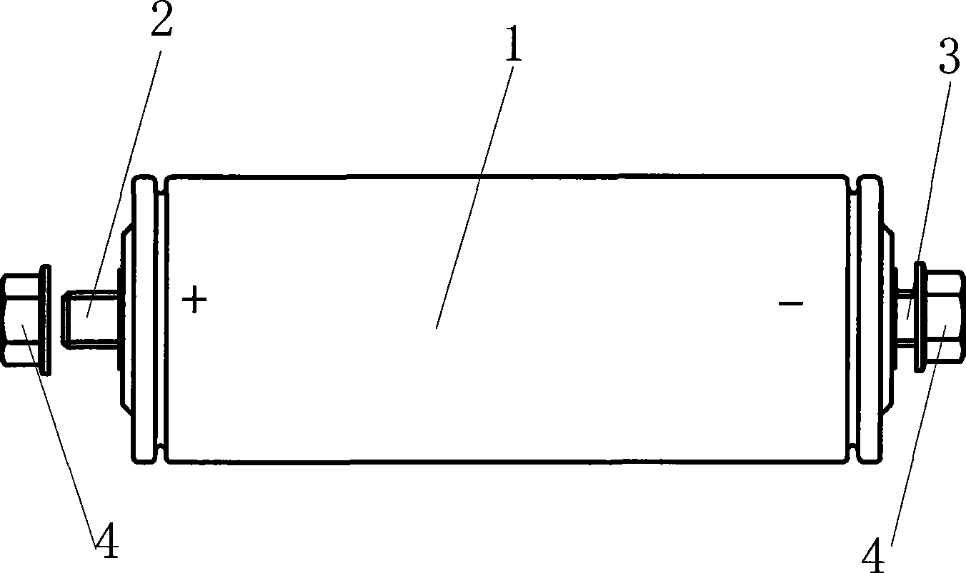
[0020] figure 1 Shown in is the battery 1 connected by the split busbar of the present invention, the positive pole and the negative pole of the battery 1 are made into the connection mode of bolt 2 and nut 4, which is convenient to better connect multiple such batteries 1 in parallel. Split busbars to form a battery pack.

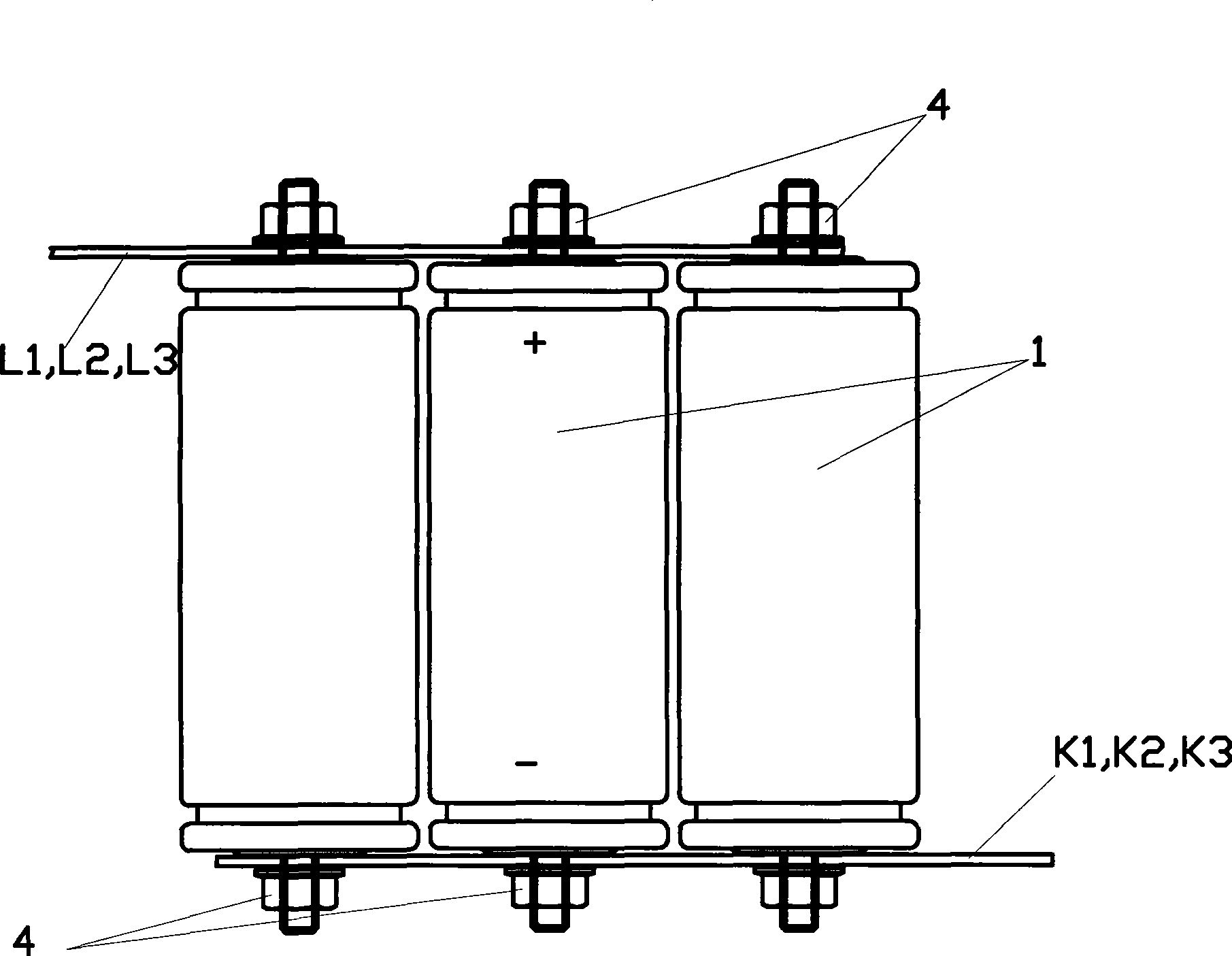
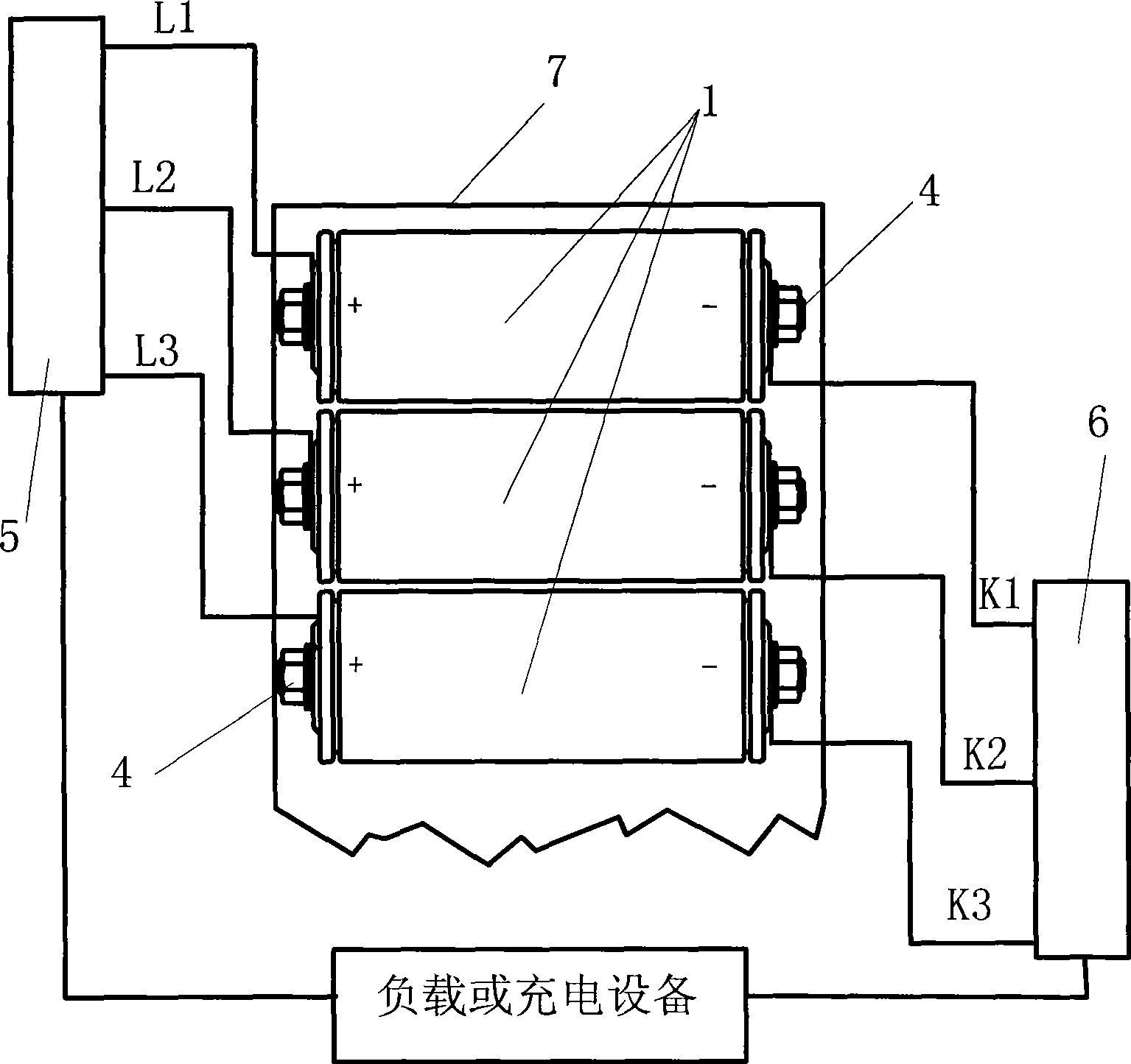
[0021] figure 2 A schematic diagram of a split busbar is shown in . Multiple batteries 1 are arranged side by side, and multiple batteries 1 (only 3 batteries are schematically shown in the figure) are connected in parallel through positive electrode split busbars L1, L2, L3 and negative electrode split busbars K1, K2, K3 , are interconnected through the holes on the busbar and the bolts and nuts 4 of each battery 1 to form a battery pack. Among them, the positive pole split busbars L1, L2, L3 lead out taps from one side, and the negative pole split busba...


PUM


Abstract

The invention discloses a split bus bar, which realizes the connection of electrodes of batteries inside battery packs, wherein the battery packs comprise a plurality of positive or negative split bus bars (L1, L2, L3, K1, K2 and K3) which are connected to corresponding batteries by connecting devices and equal in length. The split bus bar completely solves the problems of the battery packs such as unbalance current and unbalance load and prolongs the service of the battery packs.

Description

(1) Technical field [0001] The invention relates to a split bus bar, in particular to a split bus bar used in a power battery pack. (2) Background technology [0002] There are various connections in the internal connection form of the power battery pack, such as spring leaf contact, pressure contact or screw connection, but the power battery pack usually adopts the form of an integral bus bar, and multiple side-by-side batteries are arranged in parallel. The positive side and the negative side are provided with an integral bus connection to lead out the power. [0003] Although the overall busbar solves the current balance problem when the single cells in the battery pack are connected in parallel. However, once the output (input) end is connected to the external circuit, it cannot form an integral connection. That is, there can only be a point connection between the external circuit and the battery pack. As a result, the current flowing to the single cells cannot be bal...

Claims


Application Information

Patent Timeline
IPC IPC(8): H01R25/16H01M2/20H01M50/507
CPCY02E60/12Y02E60/10
Inventor 方平福王晏
Owner 王晏
Learn More