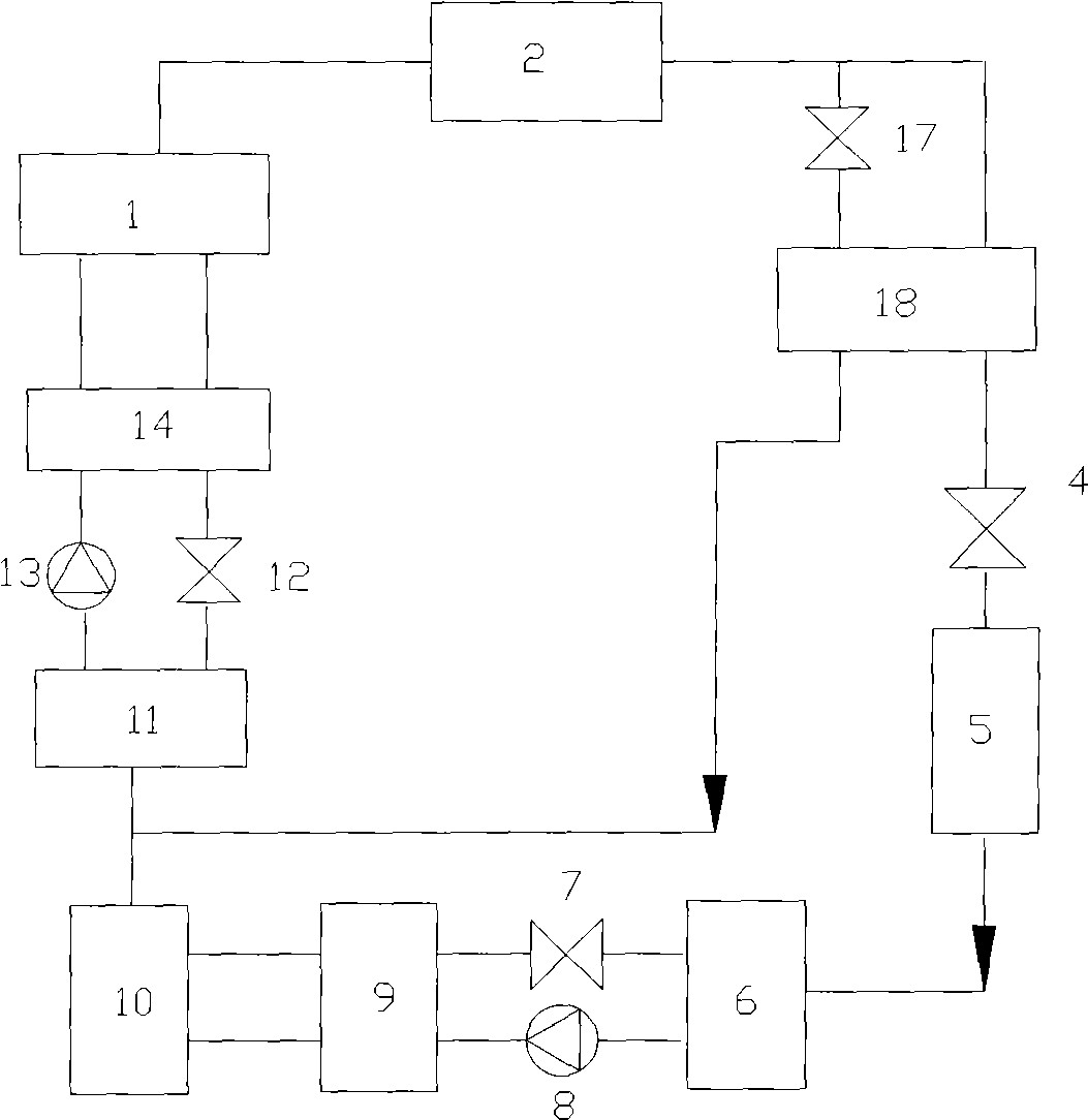
Efficient two-stage absorption refrigerating device

A technology of absorption refrigeration and high-pressure absorber, which is applied in refrigerators, adsorption machines, refrigeration and liquefaction, etc. It can solve the problems of lower system performance coefficient, low system performance coefficient, and little performance improvement, and achieve a significant performance coefficient , broad application prospects, simple structure effect

Inactive Publication Date: 2009-09-02
ZHEJIANG UNIV
View PDF0 Cites 20 Cited by
  • Summary
  • Abstract
  • Description
  • Claims
  • Application Information

AI Technical Summary

Problems solved by technology

[0003] The main disadvantage of the general single-stage absorption refrigeration device is that a higher temperature is required to obtain the cooling capacity with a lower evaporation temperature.
Some researchers have proposed a two-absorber absorption refrigeration system. The idea is to use a part of the refrigerant to cool the absorber, so that the absorber can reach a lower temperature, so that the other part of the refrigerant can be cooled. Produce higher-grade cooling capacity, but this will greatly reduce the performance

Method used


Image

  • Efficient two-stage absorption refrigerating device
  • Efficient two-stage absorption refrigerating device
  • Efficient two-stage absorption refrigerating device

Examples


Embodiment 1

[0019] Example 1 Using ammonia-water working medium as the working medium, the performance of the new device and the traditional device were simulated and calculated. Table 1 is a comparison of the performance of the new and old two-stage absorption refrigeration devices at different evaporation temperatures.

[0020] Table 1 Performance comparison of old and new two-stage refrigeration devices at different evaporating temperatures

[0021] parameter T g T k T e COP t COP n n 1 Q at Q an n 2 unit K K K / / % W W % Condition 1 375 310 238 0.820 0.093 13.5 14382 12928 10.1 Condition 2 375 310 240 0.136 0.152 11.9 9513.4 8720.2 8.33 Condition 3 375 310 242 0.157 0.175 11.2 8480.0 7831.0 7.65 Condition 4 375 310 244 0.174 0.192 10.3 7860.9 7317.6 6.91 Condition 5 375 310 246 0.186 0.204 9.46 7479.7 7009.7 6.28 Condition 6 375 310 248 0.197 0.215 8.73 7165.3...

Embodiment 2

[0029] In Example 2, the ammonia-water working medium pair was used as the assumption that the heat transfer temperature difference at the cold end of the subcooler was 5°C, and the performance of the new device and the traditional device were simulated and calculated. Table 3 shows the old and new devices at different evaporation temperatures. Comparison of the performance of two-stage refrigeration units.

[0030] Table 3 Performance comparison of old and new two-stage refrigeration devices at different evaporating temperatures

[0031] parameter T g T k T e COP t COP n n 1 Q at Q an n 2 unit K K K / / % W W % Condition 1 375 310 238 0.0820 0.0919 12.1 14382 13063 9.16 Condition 2 375 310 240 0.136 0.145 10.6 9513.5 8798.1 7.51 Condition 3 375 310 242 0.157 0.173 9.91 8480.0 7901.1 6.83 Condition 4 375 310 244 0.174 0.189 8.99 7860.9 7381.7 6.09 Condition 5 375 310 24...


PUM


Abstract

The invention discloses an efficient two-stage absorption refrigerating device. A gas outlet of a high-pressure generator in the efficient two-stage absorption refrigerating device is sequentially connected with cryogenic fluid inlets of a condenser, an intermediate heat exchanging part, a first throttle, an evaporator, a low-pressure solution pump, a low-pressure solution heat exchanger, a low-pressure generator, a high-pressure solution pump, and a high-pressure solution heat exchanger; the gas outlet of the intermediate heat exchanging part is connected with a gas inlet of a high-pressure absorber, a solution outlet of the high-pressure generator is connected with solution inlets of the high-pressure solution heat exchanger, a third throttle and the high-pressure absorber, and the solution outlet of the low-pressure generator is connected with solution inlets of the low-pressure solution heat exchanger, a second throttle and the low-pressure absorber. The invention has simple structure, obviously improves the performance factor and has wide application prospect.

Description

technical field [0001] The invention belongs to the technical field of refrigeration, and in particular relates to a high-efficiency two-stage absorption refrigeration device. Background technique [0002] Absorption refrigeration technology is a heat-driven refrigeration technology. Compared with compression refrigeration technology, its main advantage is that it only needs to consume very little electric energy and can utilize low-grade heat energy. Since Carl, a Frenchman, invented the continuous absorption refrigerator in 1860, the absorption refrigerator has been occupying an important position in the market. In recent years, as the voice of energy conservation and environmental protection has become higher and higher, absorption refrigerators have been more favored. In 2000, researchers predicted that the sales volume of absorption refrigerators in 2008 would reach 68.7 million units. [0003] The main disadvantage of the general single-stage absorption refrigeration ...

Claims


Application Information

Patent Timeline
IPC IPC(8): F25B15/04
CPCY02B30/62Y02A30/27
Inventor 陈光明洪大良唐黎明
Owner ZHEJIANG UNIV
Why Eureka
Try Eureka