Oil pipe automatic conveying device

An automatic conveying device and oil pipe technology, applied in the direction of automatic/semi-automatic lathes, turning equipment, tool holder accessories, etc., can solve the problems of unstable movement, low efficiency, single function, etc., achieve compression loading and unloading time, and improve processing efficiency , Improve the effect of product quality

Active Publication Date: 2012-02-15
宁夏新瑞长城机床有限公司
View PDF0 Cites 0 Cited by
  • Summary
  • Abstract
  • Description
  • Claims
  • Application Information

AI Technical Summary

Problems solved by technology

Some large-scale steel pipe manufacturing enterprises use imported lathes and auxiliary equipment. The auxiliary equipment is fully functional and can be adjusted automatically, with the highest efficiency, but the price is expensive, which is difficult for small and medium-sized enterprises to afford.
General enterprises use self-made simple feeders, which can only realize part of the above functions. The price is cheap, but the function is single, the control accuracy is not high, and it is difficult to ensure product accuracy and quality.
Small and medium-sized enterprises usually use the cylinder to pull the connecting rod to drive the sloping plate to stand up or lay flat to turn over the material. This way of turning over the material has discontinuous motion trajectory, unstable movement, loud noise, and easy bending and deformation of the pipe.
The feeding and discharging method adopts ordinary three-phase asynchronous motor to drive the V-shaped roller to drive the pipe fittings to feed or discharge after being decelerated by the reducer. Because the ordinary three-phase asynchronous motor cannot adjust the speed, the feeding and discharging can only be carried out at a fixed speed, and there is no high speed. The function of deceleration and positioning after approaching, the control method mostly adopts the simple and backward relay control method, the operator has high labor intensity, low efficiency and high failure rate

Method used


Image

  • Oil pipe automatic conveying device
  • Oil pipe automatic conveying device
  • Oil pipe automatic conveying device

Examples


Embodiment Construction

[0024] Below in conjunction with accompanying drawing, structure of the present invention is described in more detail:

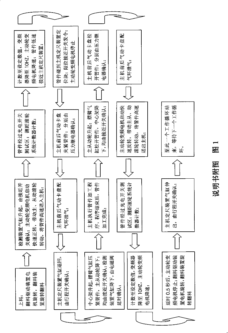
[0025] figure 1 The sequence in which the invention works is given;

[0026] The present invention consists of five parts: a walking beam device, a central beam device, a driving wheel device, a driven wheel device, and a detection device; the four parts are supported by a beam to realize the action of each part.

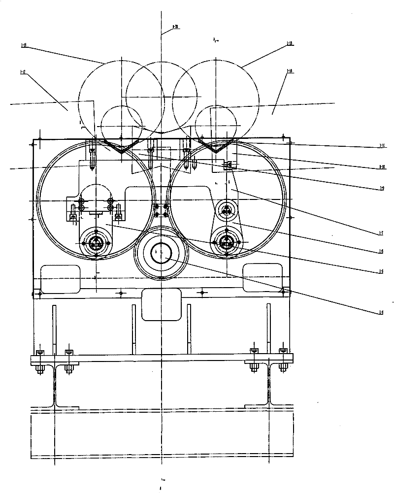
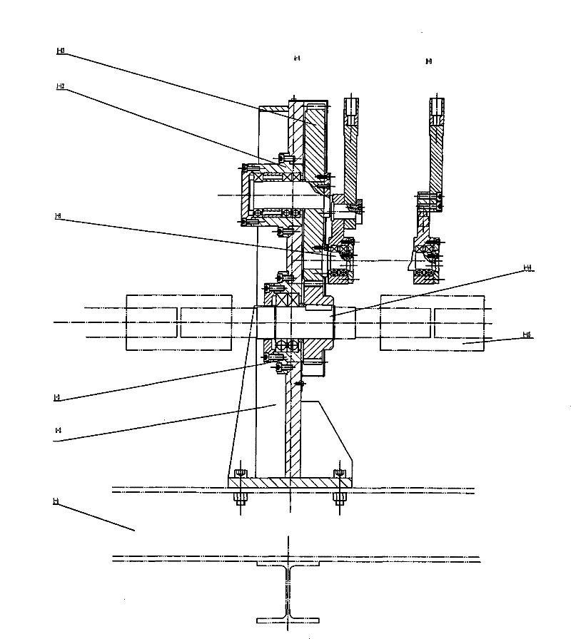
[0027] The part of the walking beam device is shown in Figure 2, and the codes in the figure are: Yan beam device 1-1, walking beam base 1-2, pinion bearing housing 1-3, pinion 1-4, support arm 1- 5. Connecting arm 1-6, feeding plate 1-7, small shaft 1-8, left V-shaped plate 1-9, right V-shaped plate 1-10, shock absorbing rubber strip 1-11, large gear bearing seat 1-12, large gear 1-13, drive shaft 1-14, coupling 1-15, feed frame 1-16, discharge frame 1-17, right V-shaped plate movement track 1-18, left The motion track of the V-shaped plate is...


PUM


Abstract

The invention relates to the technical field of mechanical processing, and belongs to auxiliary equipment of machine tools, in particular to an automatic delivery device for oil pipes. The device is composed of five parts: walking beam device, central beam device, driving wheel device, driven wheel device and detection device; the combination of five parts realizes automatic turning in and out of long tube parts, automatic feeding out When feeding and feeding, enter from the rear end of the machine tool spindle at high speed, decelerate rapidly when approaching the positioning device, and stop after triggering the switch; exit the machine tool spindle at high speed when discharging, decelerate and stop rapidly when approaching the turning position, and hang out of the machine tool spindle when the workpiece rotates Some parts perform functions such as slewing support, pressure wheel floating and pressing, and material blocking.

Description

technical field [0001] The invention relates to the technical field of mechanical processing, and belongs to auxiliary equipment of machine tools, in particular to an automatic delivery device for oil pipes. Background technique [0002] At present, the petroleum machinery industry generally uses CNC pipe thread lathes to process API oil and casing end threads, because the length of the pipe body is generally 4.88 meters to 12 meters, which is far greater than the distance between the two chucks of the machine tool spindle by about 2 meters, so Auxiliary equipment must be used to realize the automatic turning in and out of the machine tool for the pipe body, automatic feeding and discharging, high-speed entry into the main machine when feeding, and rapid deceleration when approaching the positioning device; high-speed exit from the main machine when discharging, and rapid deceleration when approaching the turning position. Functions such as workpiece rotation support hanging...

Claims


Application Information

Patent Timeline
Patent Type & Authority Patents(China)
IPC IPC(8): B23B13/00
Inventor 陈雁军张鑫刘杰欣赵军韩臣军张居济祁卫中赵新强陈光
Owner 宁夏新瑞长城机床有限公司
Why Eureka
Try Eureka