Method for manufacturing integral vacuum chamber of vacuum refining device

A technology of vacuum refining and manufacturing method, applied in the field of integral vacuum chamber manufacturing, can solve the problems of high processing cost and low processing efficiency, and achieve the effects of high processing efficiency, improving processing efficiency and reducing requirements

Inactive Publication Date: 2009-06-17
BAOSTEEL ENG & TECH GRP
View PDF2 Cites 0 Cited by
  • Summary
  • Abstract
  • Description
  • Claims
  • Application Information

AI Technical Summary

Problems solved by technology

[0006] The task of the present invention is to provide an improved integrated vacuum chamber manufacturing method for a vacuum refining device, which solves the problems of low processing efficiency and high processing cost in the traditional manufacturing of vacuum chambers

Method used


Image

  • Method for manufacturing integral vacuum chamber of vacuum refining device
  • Method for manufacturing integral vacuum chamber of vacuum refining device

Examples


Embodiment Construction

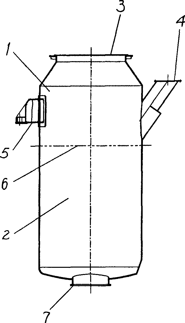
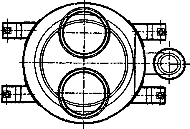
[0020] see figure 1 with figure 2 The integrated vacuum chamber of the vacuum refining device is manufactured according to the manufacturing method of the present invention, and processed according to the following steps, taking the 300-ton RH vacuum refining device as an example:

[0021] 1. Divide the integral vacuum tank chamber into two sections for manufacture. The height from the upper flange 3 to the bottom is in the range of 3000-3400mm as the upper section 1, and the height of the rest is taken as the lower section 2. The joint of the two sections is fully melted. Butt welded joints 6 and 100% ultrasonic or radiographically inspected. The height of the upper section 1 of the integral vacuum chamber from the upper flange 3 to the bottom is in the range of 3000-3400 mm, and the upper section 1 includes the upper flange surface and sealing groove, the feeding port 4 flange and the vacuum chamber support 5 .

[0022] The upper flange surface and sealing groove of the ...


PUM

PropertyMeasurementUnit
heightaaaaaaaaaa

Abstract

The present invention relates to process of making integrated vacuum chamber for vacuum refining apparatus. The making process of integrated vacuum chamber includes the separate machining of two chamber sections, including one upper section of 3000-3400 mm height and one lower section, in a common large floor-type milling and boring machine; the subsequent butt welding of two sections and annealing; and final ultrasonic or ray detection. The making process has the advantages of low production cost and high production efficiency.

Description

technical field [0001] The invention relates to a vacuum refining device in the metallurgical manufacturing industry, in particular to an integral vacuum chamber manufacturing method in the vacuum refining device adopting a vacuum cycle degassing method (RH). Background technique [0002] The vacuum tank or vacuum chamber is one of the important equipment in the RH vacuum refining device. When the vacuum tank chamber is processing molten steel, its interior is in a vacuum state, and molten steel circulates in it. When the vacuum chamber does not process molten steel, its interior returns to normal pressure. The internal temperature and pressure of the vacuum chamber fluctuate, the working conditions are harsh, the operating load is high, the reliability of the equipment is high, and the manufacturing quality must be strictly guaranteed. [0003] The main body of the vacuum chamber is welded steel structure, lined with heat insulation and refractory materials. According to...

Claims


Application Information

Patent Timeline
Patent Type & Authority Patents(China)
IPC IPC(8): C21C7/10B23P15/00
Inventor 刘安
Owner BAOSTEEL ENG & TECH GRP
Why Eureka
Try Eureka