
Rice cooker and gas-liquid separating method for the steam cylinder of rice cooker

A technology of rice cooker body and rice cooker, which is applied in the direction of pressure cooker, etc., which can solve the problems of increased manufacturing cost, low yield rate, and many parts, and achieve the effects of reducing flow rate and pressure, saving production cost, and simplifying the assembly process

Active Publication Date: 2012-05-23
PANASONIC APPLIANCES CHINA CO LTD +1
View PDF0 Cites 0 Cited by
  • Summary
  • Abstract
  • Description
  • Claims
  • Application Information

AI Technical Summary

Problems solved by technology

The shortcomings of the above structure: first, when the steam flow rate is high, the soup splashes out of the steam cylinder before it can be separated; second, the structure of the steam cylinder is complicated, there are many parts, and the required tooling and processes are complicated, which increases the manufacturing cost. low rate

Method used


Image

  • Rice cooker and gas-liquid separating method for the steam cylinder of rice cooker
  • Rice cooker and gas-liquid separating method for the steam cylinder of rice cooker
  • Rice cooker and gas-liquid separating method for the steam cylinder of rice cooker

Examples


Embodiment 1

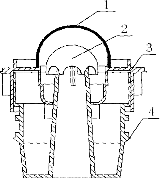
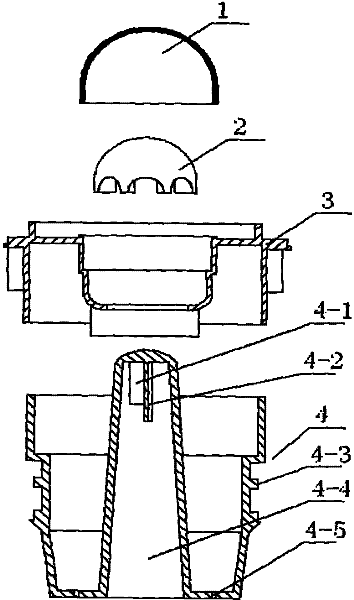
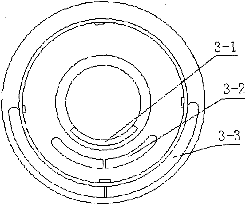
[0015] Embodiment 1: an electric rice cooker, comprising an electric rice cooker body and an outer cover of the electric rice cooker, the upper part of the outer cover of the electric rice cooker is provided with a steam cylinder, the steam cylinder is located in or on the cover of the outer cover of the electric rice cooker, and the middle part of the steam cylinder body 4 is provided with a protrusion for clamping Table 4-3. The steam cylinder body 4 is covered with a cylinder cover 3 and adopts mold injection molding. The cover surface of the cylinder cover 3 is provided with a diffuser window 3-2, and the cylinder cover body below the diffuser window 3-2 is provided with an (arc) air shield 3-1, and the cylinder cover 3 is provided with a semicircular groove along the back side 3-3. The purpose of doing like this is: the air diffuser window 3-2 can dissipate the liquid heat and the air pressure contained in the heat separated by the pneumatic rotary cover 2 through the he...

Embodiment 2

[0019] Embodiment 2: On the basis of Embodiment 1, a transparent cover 1 is provided above the pneumatic rotating cover 2. The transparent cover 1 is molded by injection molding and covered on the pneumatic rotating cover 2. The transparent cover 1 and the cylinder cover 3 are stuck together. It can not only prevent the user's fingers from touching the pneumatic rotating cover, but also facilitate the intuitive observation of the rotating state of the pneumatic rotating cover.

Embodiment 3

[0020] Embodiment 3: On the basis of Embodiment 1, the gas-liquid separation method of the steam cylinder of the electric cooker makes steam and rice water separated at the moment after being damped by the inner top of the steam channel 4-4, so that the rice water is separated by the steam channel 4-4. 4 The inner top damping directly falls back into the pot, so that the steam can push the pneumatic rotating cover 2 on the top of the steam channel 4-4 to rotate through two or more exhaust ports located on both sides of the steam channel 4-4, that is, to push the Pneumatic rotating hood 2 The blades 2-1 are driven by multiple pieces of airflow around the hood. During the rotation of the pneumatic rotating hood, the flow rate and pressure of the steam are further reduced, so that the steam is converted into a gas-liquid mixture, and the gas-liquid mixture is in the pneumatic rotating hood Under the action of the steam, the liquid in the steam is automatically separated and falls ...


PUM


Abstract

The invention relates to a rice cooker capable of reducing flow speed and realizing gas-liquid separation and a gas-liquid separating method for the steam cylinder of a rice cooker. The rice cooker coThe invention relates to a rice cooker capable of reducing flow speed and realizing gas-liquid separation and a gas-liquid separating method for the steam cylinder of a rice cooker. The rice cooker comprises a rice cooker body and a rice cooker cover, wherein a steam cylinder is arranged at the upper part of the rice cooker cover and positioned in or on the rice cooker cover, a cylinder cover is smprises a rice cooker body and a rice cooker cover, wherein a steam cylinder is arranged at the upper part of the rice cooker cover and positioned in or on the rice cooker cover, a cylinder cover is sheathed on the steam cylinder, a pneumatic rotary hood is arranged at the top of a steam passageway in the steam cylinder body, and liquid return holes are arranged in the bottom plate of the steam cyheathed on the steam cylinder, a pneumatic rotary hood is arranged at the top of a steam passageway in the steam cylinder body, and liquid return holes are arranged in the bottom plate of the steam cylinder body. The rice cooker and the gas-liquid separating method have the advantages that: firstly, the design of the pneumatic rotary cap at the top of the steam passageway in the steam cylinder bodlinder body. The rice cooker and the gas-liquid separating method have the advantages that: firstly, the design of the pneumatic rotary cap at the top of the steam passageway in the steam cylinder body not only realizes the speed reduction of steam, pressure reduction and gas-liquid separation, but also is capable of leading the separated liquid mixture to fall back directly into the rice cooker by not only realizes the speed reduction of steam, pressure reduction and gas-liquid separation, but also is capable of leading the separated liquid mixture to fall back directly into the rice cooker body and gas to be dispersed through a window radiator; and secondly, the design of the structure is novel, unique and simple, thus simplifying the assembly process and saving the production cost.ody and gas to be dispersed through a window radiator; and secondly, the design of the structure is novel, unique and simple, thus simplifying the assembly process and saving the production cost.

Description

technical field [0001] The invention relates to an electric cooker, and more specifically relates to an electric cooker capable of reducing the discharge steam flow rate and realizing vapor-liquid separation and a gas-liquid separation method for a steam cylinder of the electric cooker, which belongs to the field of electric cooker manufacturing. Background technique [0002] For the steam cylinder in the existing electric cooker, refer to the attached Figure 7 . In terms of structural design, the installation position of the steam cylinder is on the upper part of the outer cover of the electric cooker. The inside of the steam guide device set on the cover of the electric cooker is a cavity structure. The steam guide tube connected inside the body has a steam exhaust hole on the top surface; a baffle protruding downward from the inner side of the top surface of the steam guide device is provided between the steam exhaust hole and the guide tube; A backflow notch is provide...

Claims


Application Information

Patent Timeline
Patent Type & Authority Patents(China)
IPC IPC(8): A47J27/08
Inventor 乐晓辉金尾修司
Owner PANASONIC APPLIANCES CHINA CO LTD
Learn More