
A kind of upward overspeed protection device for elevator

A technology of overspeed protection and elevators, which is applied in transportation, packaging, elevators, etc., can solve the problems of tensioning device loss of function, complex structure, compressed use space, etc., and achieve the effect of ensuring stability and safety

Active Publication Date: 2021-09-03
LEAD BOSCH ELEVATOR SUZHOU CO LTD
View PDF7 Cites 0 Cited by
  • Summary
  • Abstract
  • Description
  • Claims
  • Application Information

AI Technical Summary

Problems solved by technology

[0004] Combining the above-mentioned overspeed protection device and traditional protection measures, it is based on stopping the elevator to achieve protection. On the one hand, the speed limiter is installed in the elevator machine room, and the tension wheel of the speed limiter rope is installed in the pit of the hoistway to limit the speed. The speed governor rope winds through the speed governor wheel and the tension wheel to form a fully closed loop, and its two ends are installed on the car frame through the rope head connecting frame to manipulate the lever system of the safety gear, which is not only complicated in structure, but also prone to malfunction. During operation, the wire rope slips in the groove of the speed limiter sheave, the speed limiter rope is broken or excessively slack so that the tensioning device loses its effect; on the other hand, the introduction of large equipment such as double-headed cylinders not only further compresses the use space, It will also increase the input cost

Method used


Image

  • A kind of upward overspeed protection device for elevator
  • A kind of upward overspeed protection device for elevator
  • A kind of upward overspeed protection device for elevator

Examples


Embodiment Construction

[0025] In order to more clearly illustrate the embodiments of the present invention and / or the technical solutions in the prior art, the specific implementation manners of the present invention will be described below with reference to the accompanying drawings. Obviously, the accompanying drawings in the following description are only some embodiments of the present invention, and those skilled in the art can obtain other accompanying drawings based on these drawings and obtain other implementations. In addition, the affiliation related to the orientation only indicates the relative positional relationship between the components, not the absolute positional relationship.

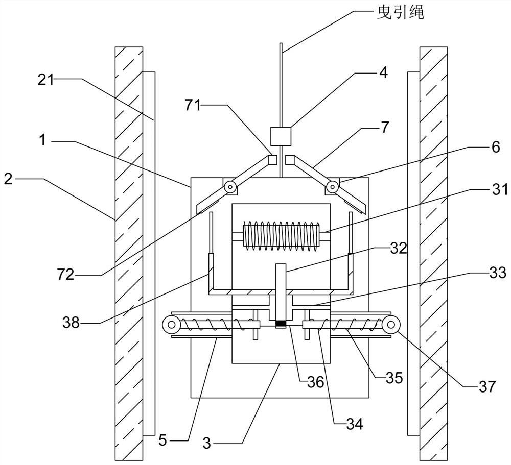
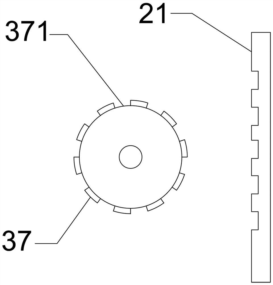
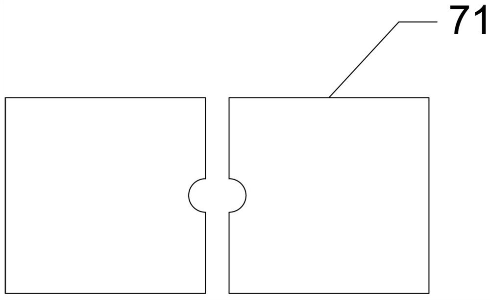
[0026] see figure 1 , figure 2 , image 3 , Figure 4 and Figure 5 , the present embodiment is used for the upward overspeed protection device of the elevator, comprising a car frame 1, an auxiliary frame 2 placed on both sides of the car frame 1, a speed limiting box 3 fixed on the back of the car f...


PUM


Abstract

The invention belongs to the technical field of low-floor elevator protection, and discloses an elevator overspeed protection device, which comprises a car frame, auxiliary frames placed on both sides of the car frame, a speed limiter box fixed on the back of the car frame, and a The speed detector above the car frame, the speed limiter box has a built-in iron core with externally wound conductive windings, an adsorption piece placed under the iron core, and a fixed guide plate symmetrically arranged on both sides of the adsorption piece. The guide rod of the speed limiter box and the elastic piece wound around the guide rod body, one end of the guide rod is connected with a traction rope wound around the bottom of the adsorption piece, and one end of the guide rod facing the auxiliary frame is provided with a guide wheel; When the speed of the floor elevator is too fast during the upward process, energize the iron core with the external conductive winding to attract the suction part, and push the traction rope wound around the bottom of the suction part through the fixed guide plate to move vertically downward until it is separated from the suction part, and then The guide wheel is ejected from the elastic piece to the auxiliary frame to increase the resistance, so as to realize the elevator deceleration.

Description

technical field [0001] The invention belongs to the technical field of protection of low-floor elevators, and in particular relates to an upward overspeed protection device for elevators. Background technique [0002] With the development of society, the use of elevators has become more and more common. It has been used only in commercial buildings and hotels, and has been used in office buildings, residential buildings and other places. Vertical elevators are the most common. Popularity has brought convenience to people's lives, but the accompanying elevator accidents have gradually increased, and people have begun to pay more and more attention to the safety protection measures of vertical elevators. Elevators generally include four major spaces and eight systems. The four major spaces include the machine room part, the shaft and the pit part, the car part and the landing part. The eight major systems generally include the traction system, the guidance system, the car syst...

Claims


Application Information

Patent Timeline
Patent Type & Authority Patents(China)
IPC IPC(8): B66B5/06B66B5/18
CPCB66B5/06B66B5/18B66B5/185
Inventor 陈琴剑蔡渊王斌
Owner LEAD BOSCH ELEVATOR SUZHOU CO LTD
Learn More