
Automatic lifting material rest

An automatic lifting and racking technology, which is applied in the direction of accumulating material equipment, metal processing equipment, manufacturing tools, etc., can solve the problems of increased impact force, increased vertical height, increased frequency of pipe transfer, etc., to improve bruises, reduce Shock force and volume reduction effect

Inactive Publication Date: 2009-08-26
TAICANG JINXIN COPPER TUBE CO LTD
View PDF0 Cites 5 Cited by
  • Summary
  • Abstract
  • Description
  • Claims
  • Application Information

AI Technical Summary

Problems solved by technology

[0003] The pipe material frame in the prior art has the following disadvantages in combination: 1. Although a relatively soft wood pad is used, the impact force between the pipe wall and the wood pad is still very large, and the defect cannot be completely eliminated; 2. If you want to reduce If the impact force is applied, the vertical height must be reduced, resulting in an increase in the frequency of transferring pipes, which is time-consuming and laborious, and the efficiency is low; if the frequency of transferring pipes is to be reduced, the vertical height must be increased, resulting in an increase in the impact force and product quality problems

Method used


Image

  • Automatic lifting material rest
  • Automatic lifting material rest
  • Automatic lifting material rest

Examples


Embodiment Construction

[0014] The present invention will be further described below in conjunction with the accompanying drawings and specific embodiments.

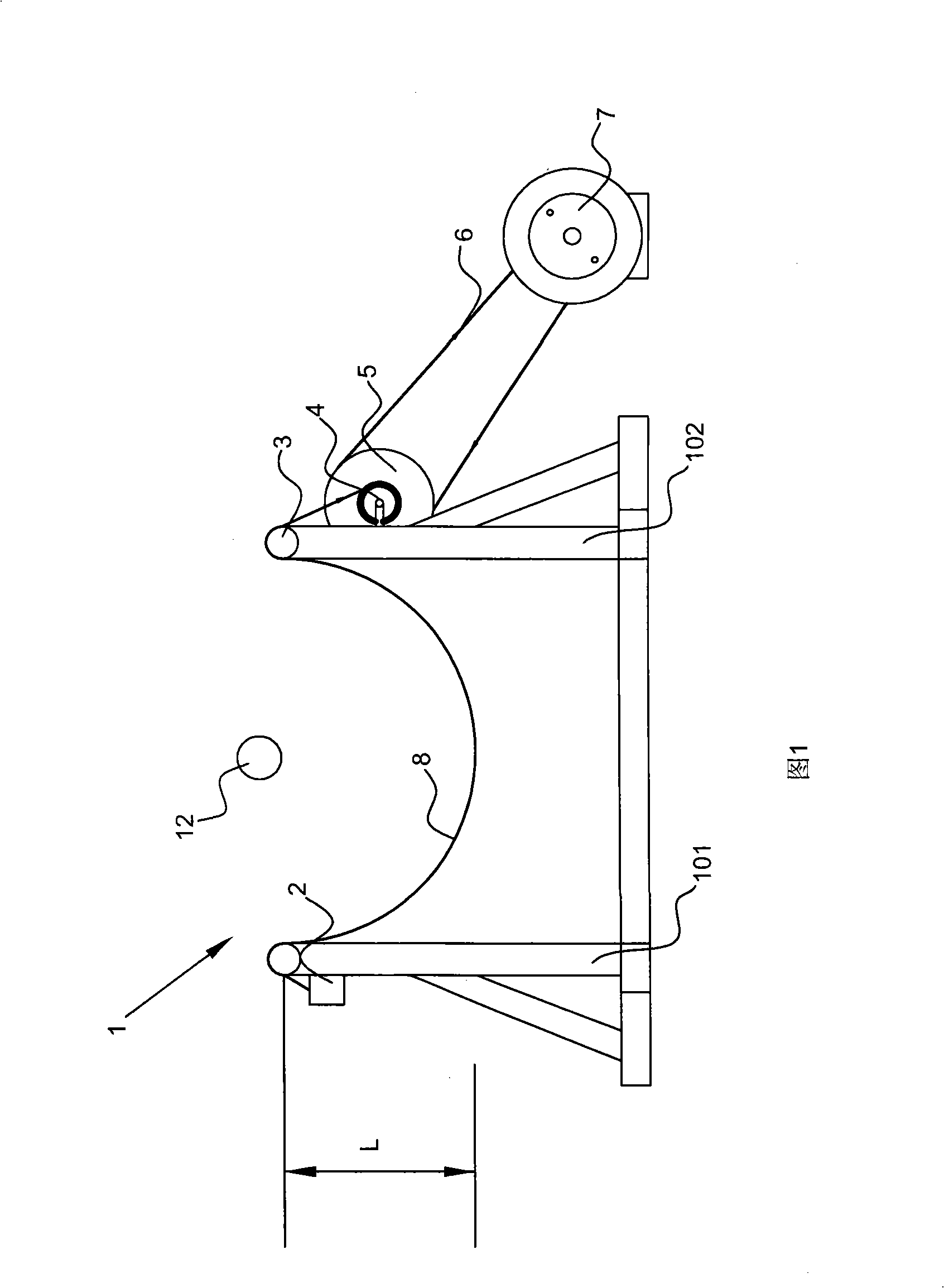
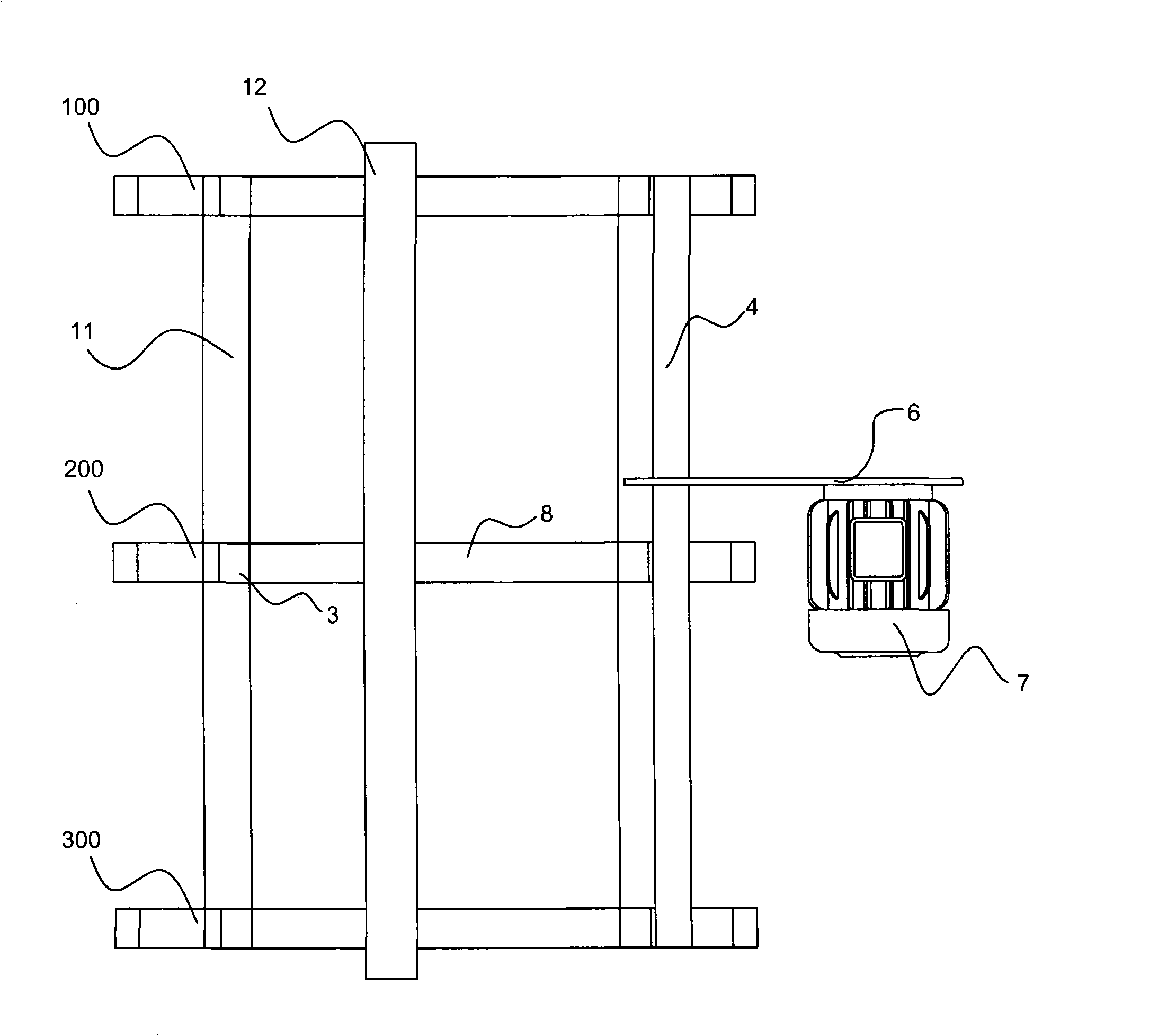
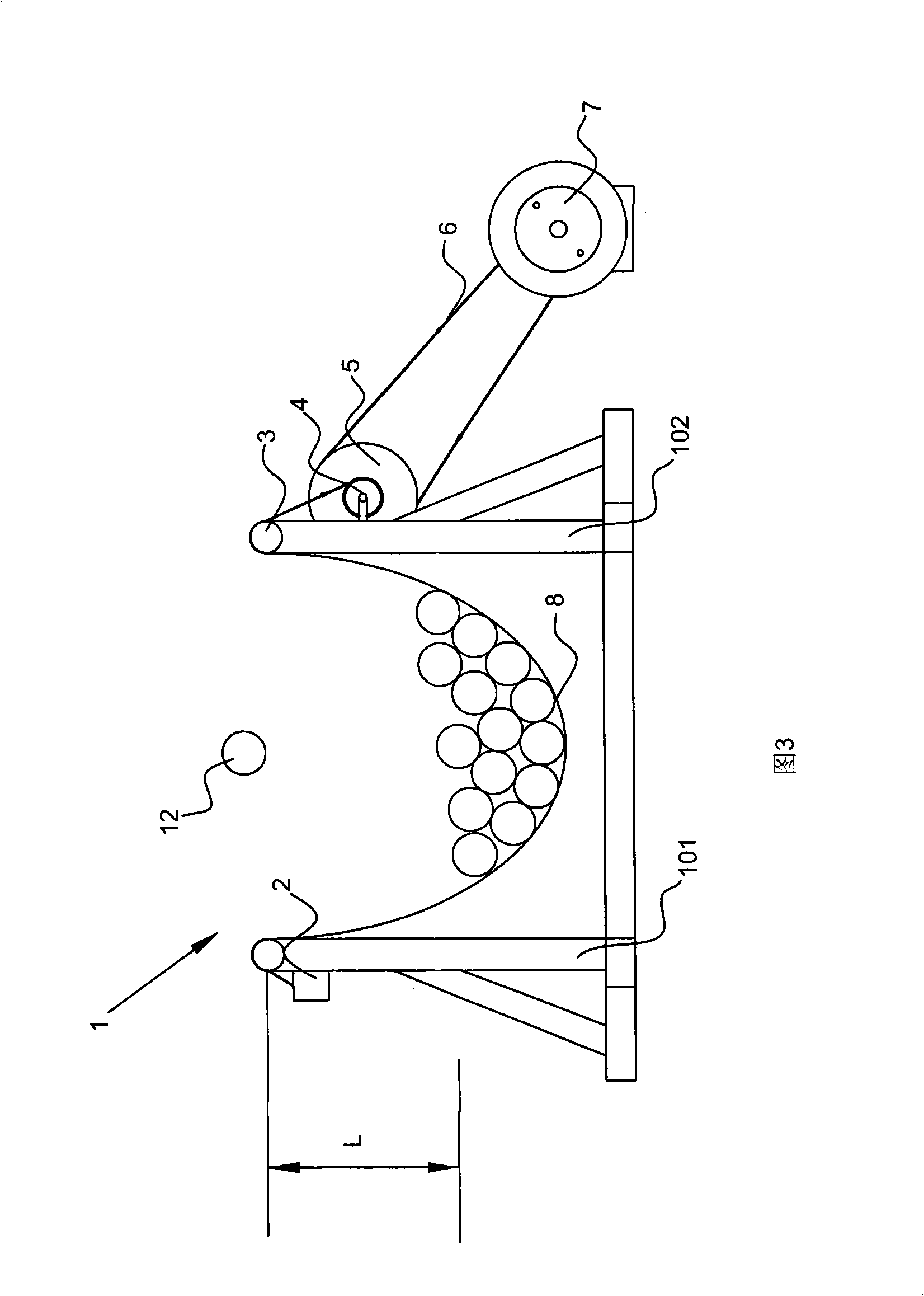
[0015] as attached figure 1 to attach image 3 As shown, the automatic lifting rack in this embodiment is composed of three "U"-shaped first units 100, second units 200 and third units 300. The above-mentioned first unit 100, second unit 200 and third unit The three units 300 are fixedly connected to each other through the bottom connecting piece 11 to increase the stability of the entire rack; two pillars 101, 102 are vertically fixed on the first unit 100, the second unit 200 and the third unit 300 respectively, Rollers 3 for reducing the friction between the carrier tape 8 and the pillars 101, 102 are respectively arranged on the tops of the pillars 101, 102, and a carrier tape fixing for fixing the carrier tape 8 is arranged on the pillar 101. The carrier 2 is provided with a carrier tape winding shaft 4 on the pillar 102. One end of the ...


PUM


Abstract

The invention discloses an automatic lifting material rest, which comprises at least two stander units arranged along the same straight line, wherein each stander unit comprises two vertically arranged struts; the tops of the two struts are provided with a roller wheel respectively for reducing the friction between a material-carrying belt and the struts; one of the struts is provided with a material-carrying belt fixer, while the other one is provided with a material-carrying belt coiling shaft; one end of the material-carrying belt is fixed on the material-carrying belt fixer, while the other end rounds two roller wheels in turn and is coiled on the material-carrying belt coiling shaft; the material-carrying belt forms a material-carrying space above the middle part between the two struts; and the material-carrying belt coiling shaft is also provided with a driving wheel coaxially, and the driving wheel is connected with a motor through a driving belt; and the material-carrying space can be increased or reduced along with the rotation of the material-carrying belt coiling shaft. The invention solves the problems in the prior art and provides the automatic lifting material rest which is simple and reliable and has remarkable effect.

Description

technical field [0001] The invention relates to a rack for collecting pipes in production. Background technique [0002] In the production and processing of various pipes, the pipes after cutting need to be collected by the material rack, and then removed from the material rack uniformly after reaching a certain amount. Since the pipe is a product that is easily deformed, it is extremely sensitive to impact, especially for high-precision pipes, it is necessary to reduce the impact as much as possible, so the capacity and impact must be considered at the beginning of the design of the rack. Such as image 3 As shown, it is a kind of pipe material collection rack widely used at present. The cross section of the entire material rack is "U" shape. The pipe material 12 falls into the material rack from above. The side wall and the bottom surface are provided with a layer of wooden pads 9 to buffer the impact force of the pipes 12 after they fall freely, and the pipes 12 are empt...

Claims


Application Information

Patent Timeline
Patent Type & Authority Applications(China)
IPC IPC(8): B21C49/00
Inventor 王宏
Owner TAICANG JINXIN COPPER TUBE CO LTD
Learn More