
Method to improve mask critical dimension uniformity (cdu)

An etching and substrate technology, applied in the photoengraving process of the pattern surface, the original for photomechanical processing, optics, etc., which can solve the problem of inability to compensate for CDU errors.

Inactive Publication Date: 2009-08-19
TAIWAN SEMICON MFG CO LTD
View PDF2 Cites 0 Cited by
  • Summary
  • Abstract
  • Description
  • Claims
  • Application Information

AI Technical Summary

Problems solved by technology

However, this solution presents several disadvantages: (1) the ion-radical barrier does not change automatically or easily; (2) the support structure (multiple legs) for the ion-radical barrier can lead to generation of particles, especially those caused by vibration; and (3) the inability of ion-radical barriers to compensate for CDU errors for all masks, especially the overall loading effects of processes other than etching (e.g., bake, develop, and exposure process)

Method used


Image

  • Method to improve mask critical dimension uniformity (cdu)
  • Method to improve mask critical dimension uniformity (cdu)
  • Method to improve mask critical dimension uniformity (cdu)

Examples


Embodiment Construction

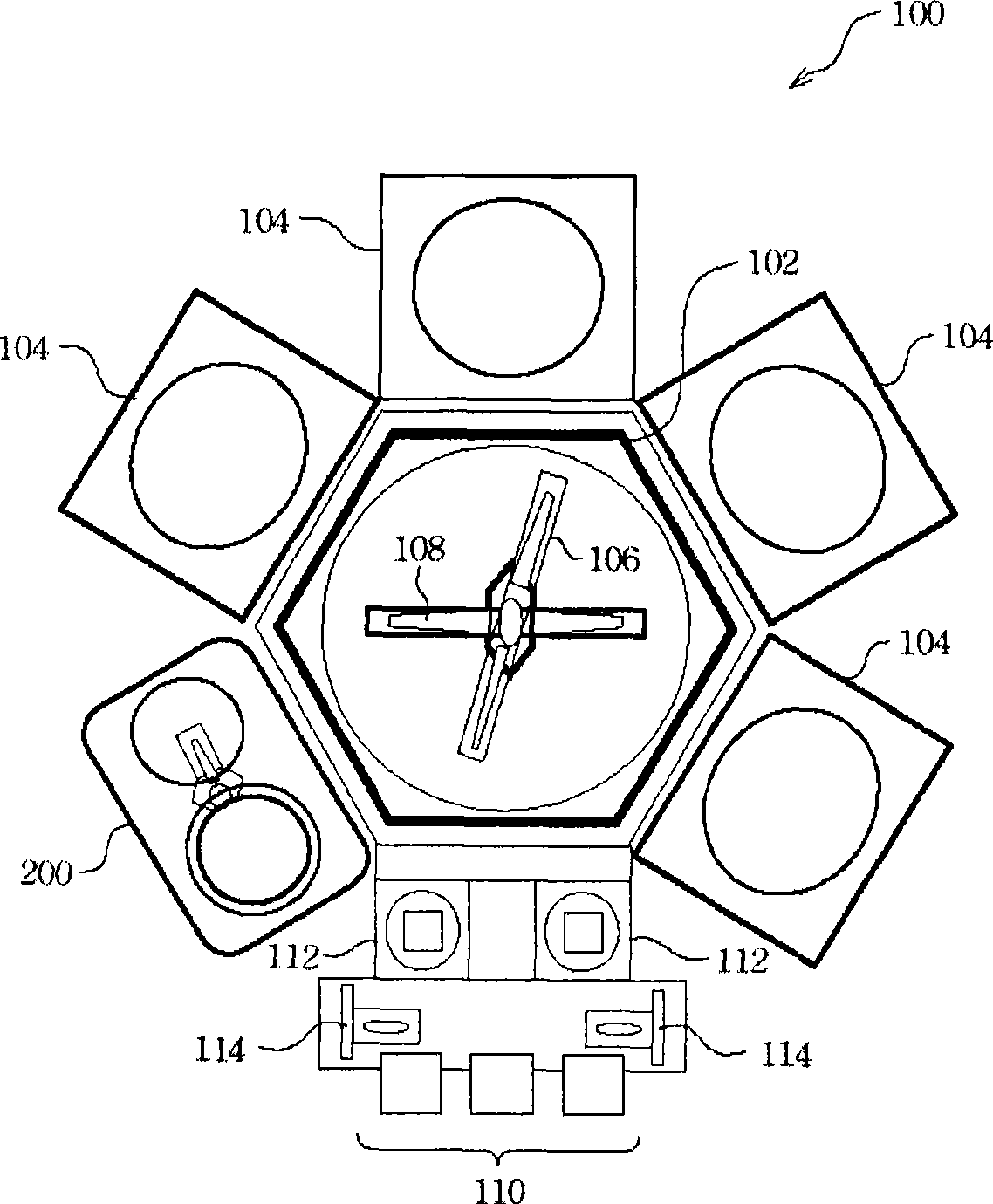
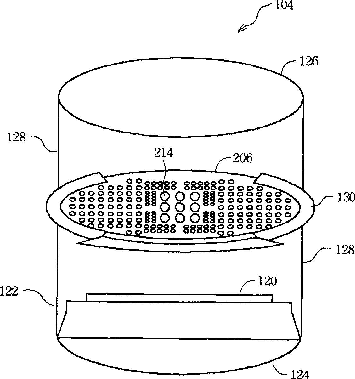
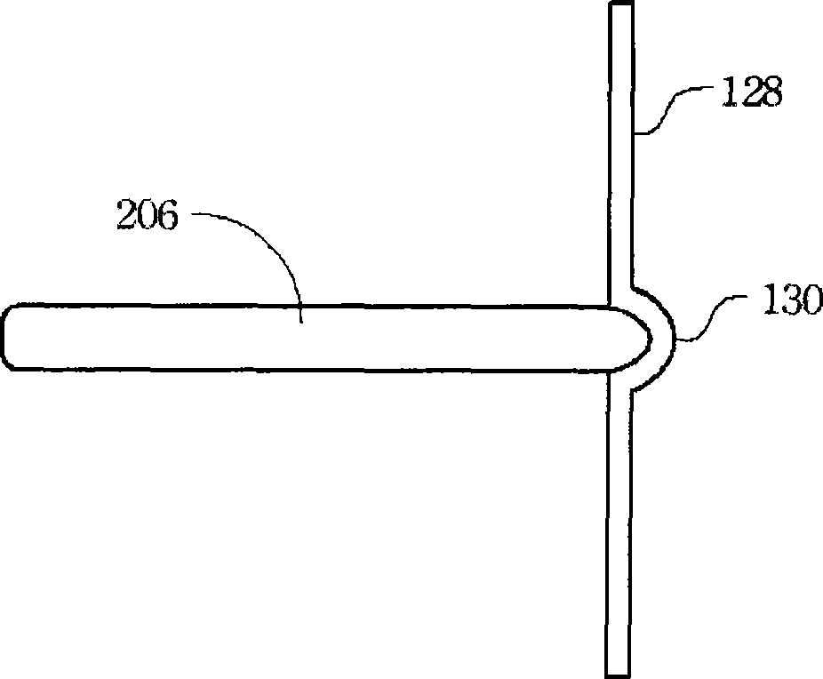
[0072] In order to further explain the technical means and effects that the present invention takes to achieve the intended purpose of the invention, the specific implementation, structure and characteristics of the method and system for etching a substrate proposed according to the present invention will be described below in conjunction with the accompanying drawings and preferred embodiments. and its efficacy are described in detail below.

[0073] It is to be understood that the following description provides many different embodiments, or examples of implementing different features of the invention. The components and arrangements of specific embodiments discussed below merely simplify the present disclosure. Certainly, the above-mentioned embodiments are only examples, and are not intended to limit the scope of the present invention. In addition, figure numbers and / or characters are repeated in different embodiments of the present invention. The purpose of repetition i...


PUM


Abstract

A method and system for fabricating a substrate is disclosed. First, a plurality of process chambers are provided, at least one of the plurality of process chambers adapted to receive at least one plasma filtering plate and at least one of the plurality of process chambers containing a plasma filtering plate library. A plasma filtering plate is selected and removed from the plasma filtering plate library. Then, the plasma filtering plate is inserted into at least one of the plurality of process chambers adapted to receive at least one plasma filtering plate. Subsequently, an etching process is performed in the substrate.

Description

technical field [0001] The present invention relates to the field of substrate manufacturing process, in particular to a method and system for etching a substrate to improve critical dimension uniformity (CDU). Background technique [0002] In semiconductor manufacturing technology, a mask (also referred to as a photomask, photomask or reticle) is used in a lithography system to expose a pattern on a substrate. A pattern may include many small or dense features defined by a critical dimension (CD). Critical dimensions define such as gate width, smaller line width or smaller line spacing allowed by the device process. As the critical dimensions of masks or wafers get smaller (eg, from 45nm to 32nm), it is important that the dimensional and geometric variations of the pattern features also get smaller. The above-mentioned differences in pattern features will cause errors in critical dimension uniformity (CDU). [0003] Variations in size and geometry of pattern features are...

Claims


Application Information

Patent Timeline
IPC IPC(8): G03F1/00
CPCH01J37/32422H01L21/67207H01L21/67236H01L21/67167G03F1/36G03F1/32G03F1/80
Inventor 黄义雄吕启纶李宏仁秦圣基辜耀进
Owner TAIWAN SEMICON MFG CO LTD
Learn More