Alternating current motor drive circuit and electric vehicle drive circuit

An AC motor and drive circuit technology, applied in the direction of AC motor control, engine-driven traction, electric vehicles, etc., can solve the problems of difficult miniaturization, difficult circuit miniaturization, and circuit large-scale, to improve performance and conversion efficiency. good effect

Active Publication Date: 2009-08-12
NAT UNIV CORP NAGAOKA UNIV TECH +1
View PDF2 Cites 8 Cited by
  • Summary
  • Abstract
  • Description
  • Claims
  • Application Information

AI Technical Summary

Problems solved by technology

[0006] In addition, in Figure 10 In this case, it is necessary to use a large-capacity capacitor for the capacitor 13 for smoothing DC, and it is difficult to miniaturize the circuit
In addition, the reactor L1 is required in the DC chopper circuit 12, which also has the problem of increasing the size of the circuit.
[0007] On the other hand, in Figure 11 In this case, it is also necessary to use a large DC capacitor C2 between the battery 12 and the motor generator MG2, making it difficult to miniaturize
In addition, the reactor L needs to be used in the DC chopper circuit 32, which also has the problem of increasing the size of the circuit.

Method used


Image

  • Alternating current motor drive circuit and electric vehicle drive circuit
  • Alternating current motor drive circuit and electric vehicle drive circuit
  • Alternating current motor drive circuit and electric vehicle drive circuit

Examples


Embodiment Construction

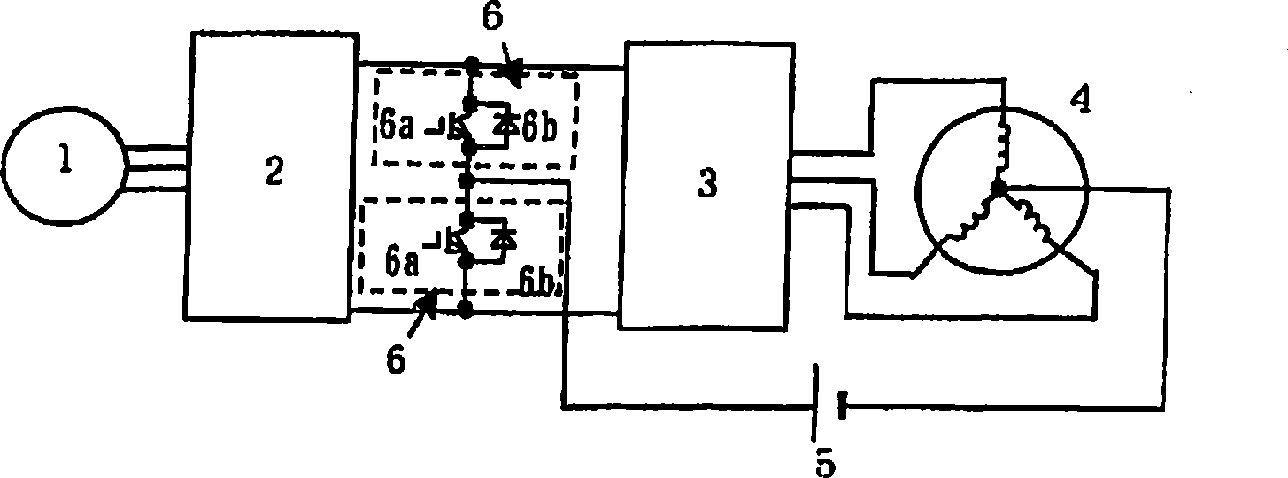
[0040] figure 1 It is a configuration diagram showing an embodiment of the present invention.

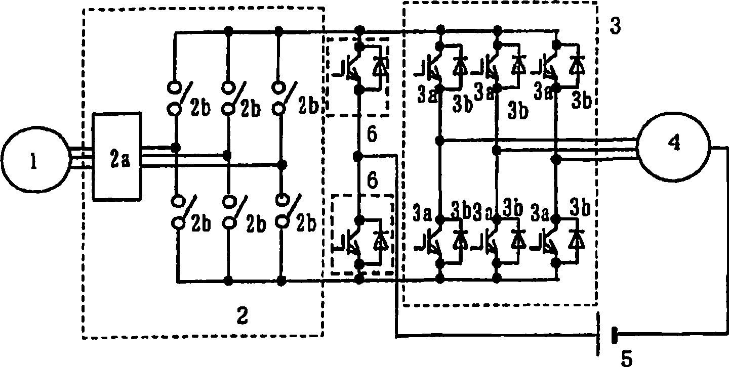
[0041] As shown in the figure, in this example, a current-source rectifier circuit 2 and a voltage-source inverter 3 are connected to the output of a three-phase AC generator 1, and an AC motor 4 is driven by the output thereof. For example, as disclosed in Non-Patent Document 2, the combination of a current-type rectifier circuit 2 and a voltage-source inverter 3 is called an indirect matrix converter (Indirect Matrix Converter), etc., and a current-type rectifier circuit is used as the rectifier circuit. This does not require the use of Figure 10 Large components such as the capacitor 13 shown.

[0042] In addition, two bridge arms 6 in which a switching element 6 a and a diode 6 b are connected in antiparallel are connected in series to the output of the rectifier circuit 2 . And, the positive terminal of the storage battery 5 is connected to the middle point of the two bridg...


PUM


Abstract

To eliminate a need for a large volumetric reactor in a direct current chopper, achieving a downsizing of the circuit. A current source rectifier circuit (2) is provided at an output of an alternating current generator (1), an alternating current motor (4) is connected to an output of the rectifier circuit (2) via a voltage source inverter (3), furthermore, two arms (6) having switching elements connected in inverse parallel to diodes are connected to the output of the rectifier circuit (2), and one terminal of a direct current power source (5) capable of a power supply and absorption is connected to a midpoint between the arms (6), while the other terminal thereof is connected to a neutral point of motor coils, achieving a solution of the problem.

Description

technical field [0001] The present invention relates to an AC motor drive circuit for driving an AC motor using an AC generator and a DC power supply capable of supplying and absorbing electric power, and an electric vehicle drive circuit using the drive circuit. Background technique [0002] Conventionally, as such a circuit, known such as Figure 10 Such a circuit (for example, Patent Document 1). [0003] Figure 10 It is a circuit diagram showing a first conventional example. The three-phase output of the alternator M2 is converted into a direct current by a voltage-type rectifier circuit 31, and the direct current is smoothed by a capacitor 13. The voltage-type rectifier circuit 31 pairs switching elements Each bridge arm connected in antiparallel with the diode is formed by bridge connection. In addition, a DC chopper circuit ( チヨツパ circuit) 12 to supply and receive electric power between them. And, the AC motor M1 is driven from the above-mentioned DC through the ...

Claims


Application Information

Patent Timeline
Patent Type & Authority Applications(China)
IPC IPC(8): H02P27/06H02M7/00B60L50/15H02M7/48
CPCY02T10/642B60L2210/42Y02T10/7005Y02T10/725H02P27/04Y02T10/7241B60L2210/20H02M7/217H02P9/48Y02T10/70B60L11/18B60L50/60Y02T10/64Y02T10/72
Inventor 伊东淳一岩堀道雄鹢头政和
Owner NAT UNIV CORP NAGAOKA UNIV TECH
Why Eureka
Try Eureka