Disk-type brake

A technology of disc brakes and brake pads, applied in the direction of brake types, axial brakes, brake components, etc., can solve the problem of unstable posture of brake pads, increase of piston arrangement distance, triangle defect of torque receiving part, etc. question

Inactive Publication Date: 2002-10-23
HITACHI LTD
View PDF1 Cites 6 Cited by
  • Summary
  • Abstract
  • Description
  • Claims
  • Application Information

AI Technical Summary

Problems solved by technology

In other words, due to the unique triangular shape of the torque receiving part between the pistons, the thickness of the outer peripheral side of the support frame is very thick, so the arrangement pitch of the pistons is increased, and the support frame is enlarged and heavy.
[0005] In addition, if the wall thickness of the torque receiving portion between the pistons is reduced only to reduce the arrangement pitch of the pistons, there will be a new problem that the triangular front end side of the torque receiving portion is missing and cannot fully The length of the torque receiving part is ensured, and the posture of the brake pad is unstable during braking

Method used


Image

  • Disk-type brake
  • Disk-type brake
  • Disk-type brake

Examples


Embodiment Construction

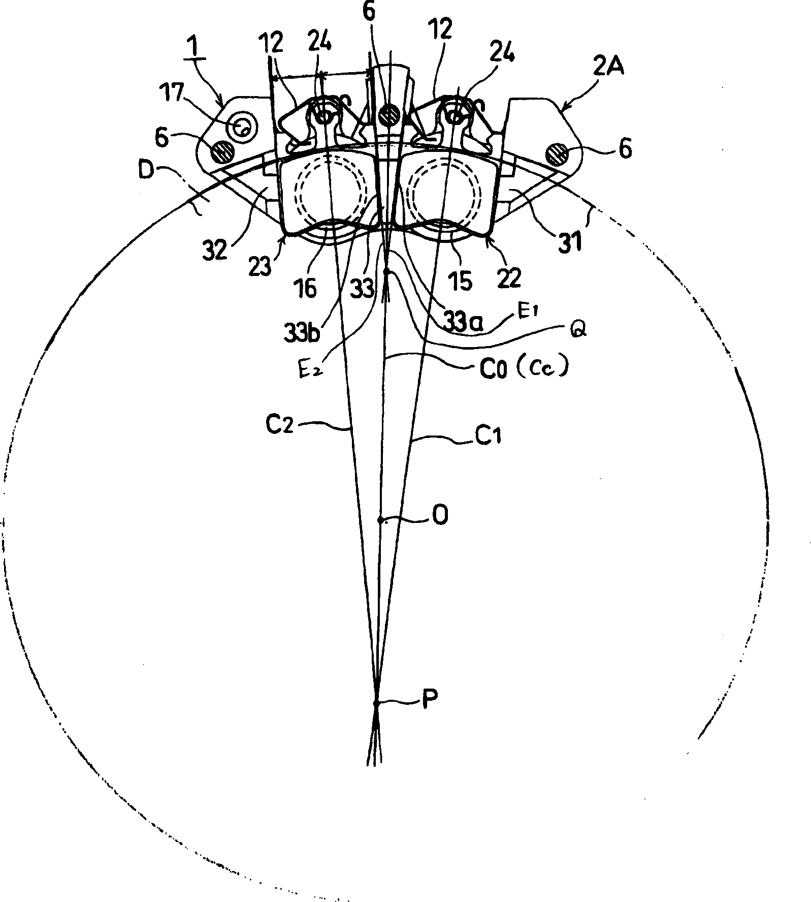
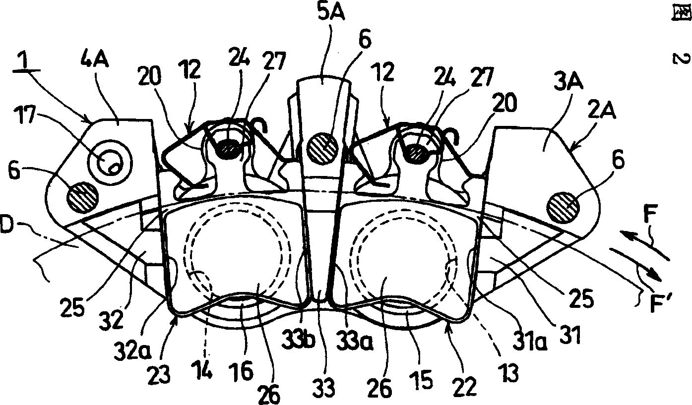
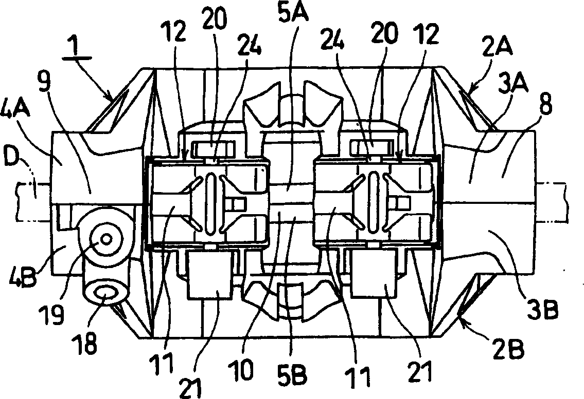
[0022] Embodiments of the present invention will be described below with reference to the drawings.

[0023] Figure 1 to Figure 7 Example 1 of the present invention is shown. As the disc brake of this embodiment 1, it is a fixed support frame, and its overall structure is shown in Figure 2- Figure 4 shown. In these figures, reference numeral 1 is a holder main body, and the holder main body 1 comprises an inner side holder half body 2A arranged inside the disk swivel D (vehicle inside) and a half body 2A arranged outside the disk turn D (vehicle outside). The outer support frame half body 2B is butted and connected as a whole. More specifically, each holder half body 2A and 2B has protrusions 3A, 4A protruding in the axial direction of the disc rotor D at three positions on both sides and the center along the circumferential direction of the disc rotor D. , 5A and 3B, 4B, 5B, in the state where these opposite protrusions 3A and 3B, 4A and 4B, 5A and 5B are butted against...


PUM


Abstract

A disc brake, which can reduce the wall thickness of the torque receiving part between the pistons to the greatest extent without sacrificing the length, the disc brake has multiple pairs of pistons (15, 16) on both sides of the disc rotating body, through which each The advancement of the pistons (15, 16) makes many pairs of brake blocks (22, 23) crimped on the disc rotating body (D), and at the same time, the sides of each pair of brake blocks (22, 23) are supported on the support Braking forces are generated on the torque receiving parts (31, 32, 33) of the frame main body (1), and each pair of brake blocks (22, 23) is configured as follows: in the radial direction of the disc rotation body (D), in the opposite direction The rotation center (O) of the disk rotation body (D) and a point (P) in the area on the opposite side of the support frame main body (1), the centerlines of each block intersect, and the torque receiving part (33 in the middle) is reduced as much as possible ) at the front end angle of the triangle to reduce the arrangement spacing of the pistons (15, 16).

Description

technical field [0001] The present invention relates to disc brakes for motor vehicle braking, and more particularly to disc brakes for two-wheeled motor vehicles. Background technique [0002] Disc brakes for two-wheeled motor vehicles have the following brakes. On the main body of the support frame that contains a plurality of pistons arranged at least on one side of the disc rotating body along its rotation direction, it is slidable to support the pistons corresponding to the pistons. There are many pairs of brake blocks on both sides of the disc rotation body. With the advancement of the pistons, each pair of brake blocks is crimped on the disc rotation body. side of the brake block, thereby generating braking force. In addition, the pistons are disposed opposite to each other on both sides of the disc rotor in the bracket-fixed type disc brake, and are disposed only on one side of the disc rotor in the bracket-floating type disc brake. [000...

Claims


Application Information

Patent Timeline
IPC IPC(8): F16D65/14
CPCF16D65/095F16D65/18F16D2055/002F16D2055/0091
Inventor 南里圭介佐野隆志村幸利
Owner HITACHI LTD
Why Eureka
Try Eureka