Screw tightening device and torque sensor

A torque sensor and fastening device technology, which is applied in measuring devices, torque measurement, instruments, etc., can solve problems such as difficulty in one-handed operation, achieve the effects of reducing reaction force, increasing torque, and reducing burden

Inactive Publication Date: 2011-08-17
HONDA MOTOR CO LTD
View PDF3 Cites 7 Cited by
  • Summary
  • Abstract
  • Description
  • Claims
  • Application Information

AI Technical Summary

Problems solved by technology

In addition, if the required tightening torque increases, the reaction force will also increase, making it difficult to work with one hand.

Method used


Image

  • Screw tightening device and torque sensor
  • Screw tightening device and torque sensor
  • Screw tightening device and torque sensor

Examples


Embodiment Construction

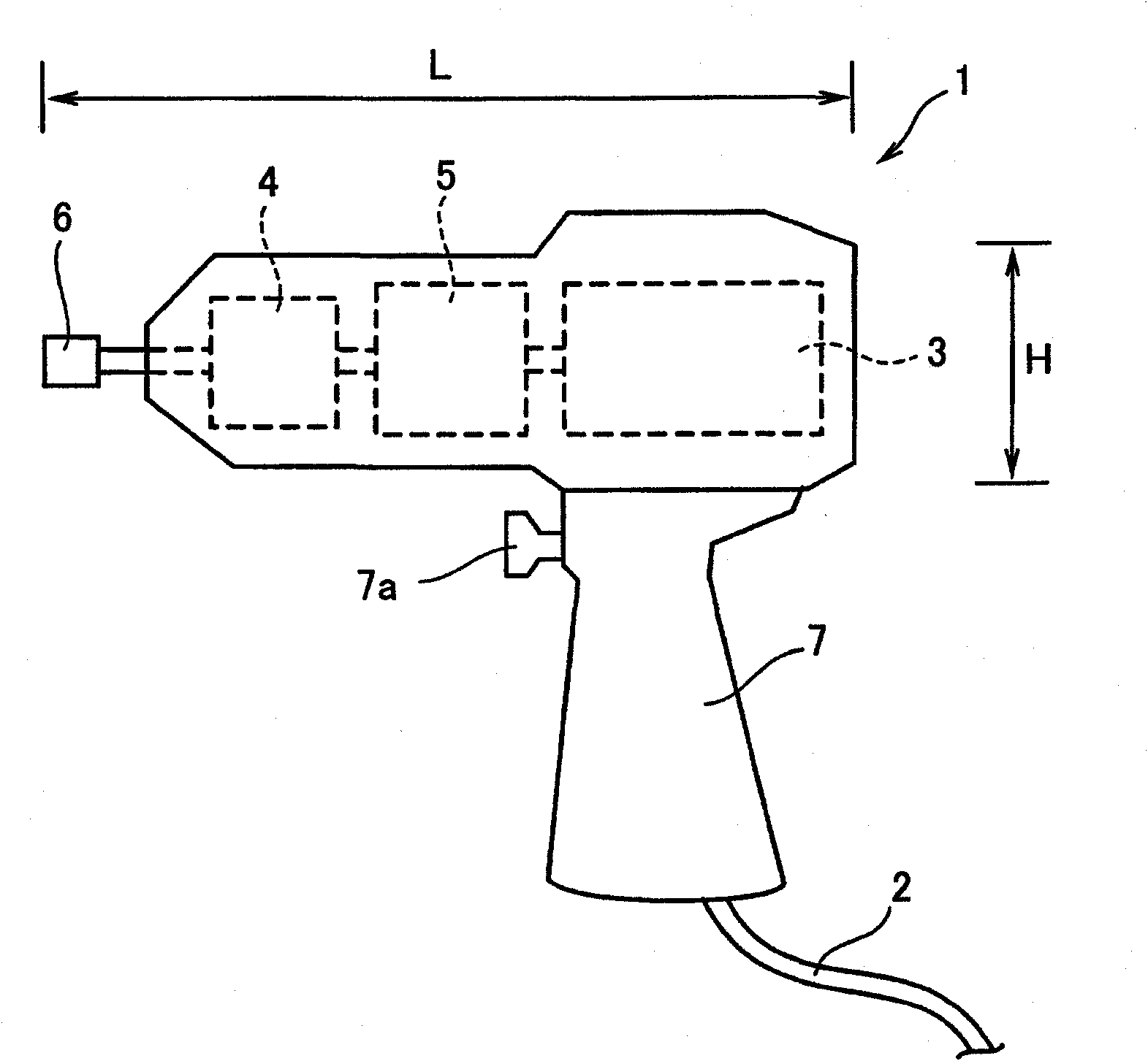
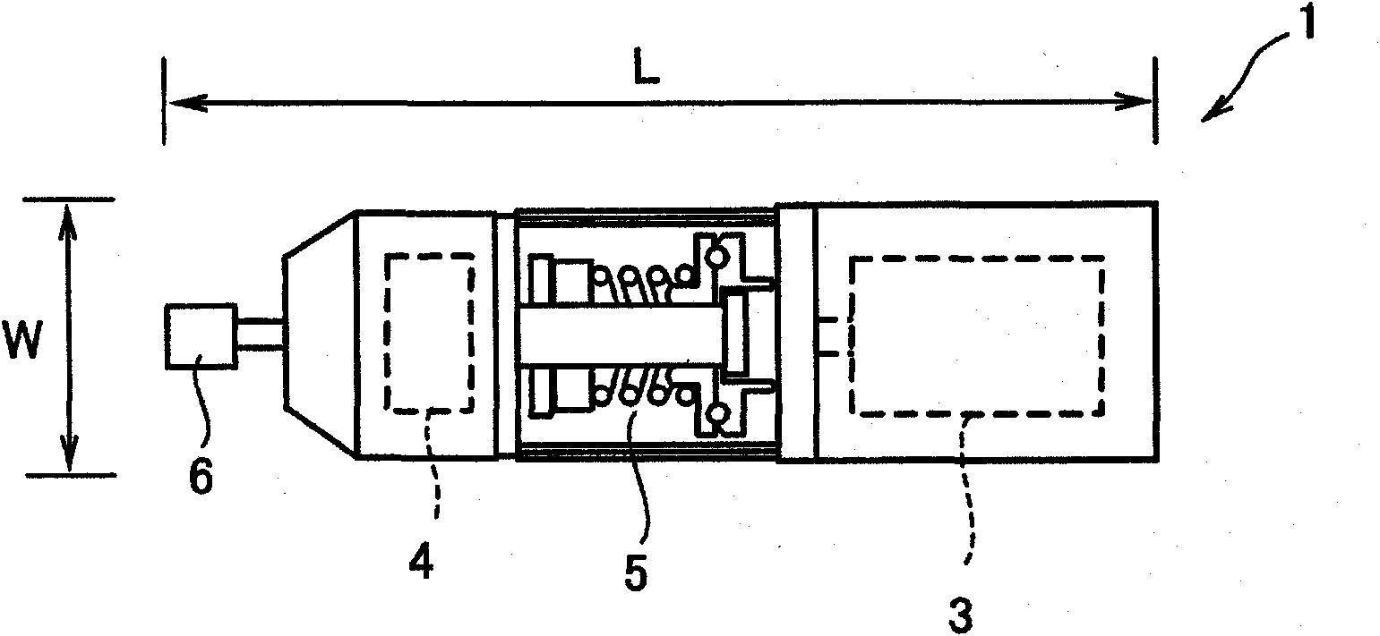
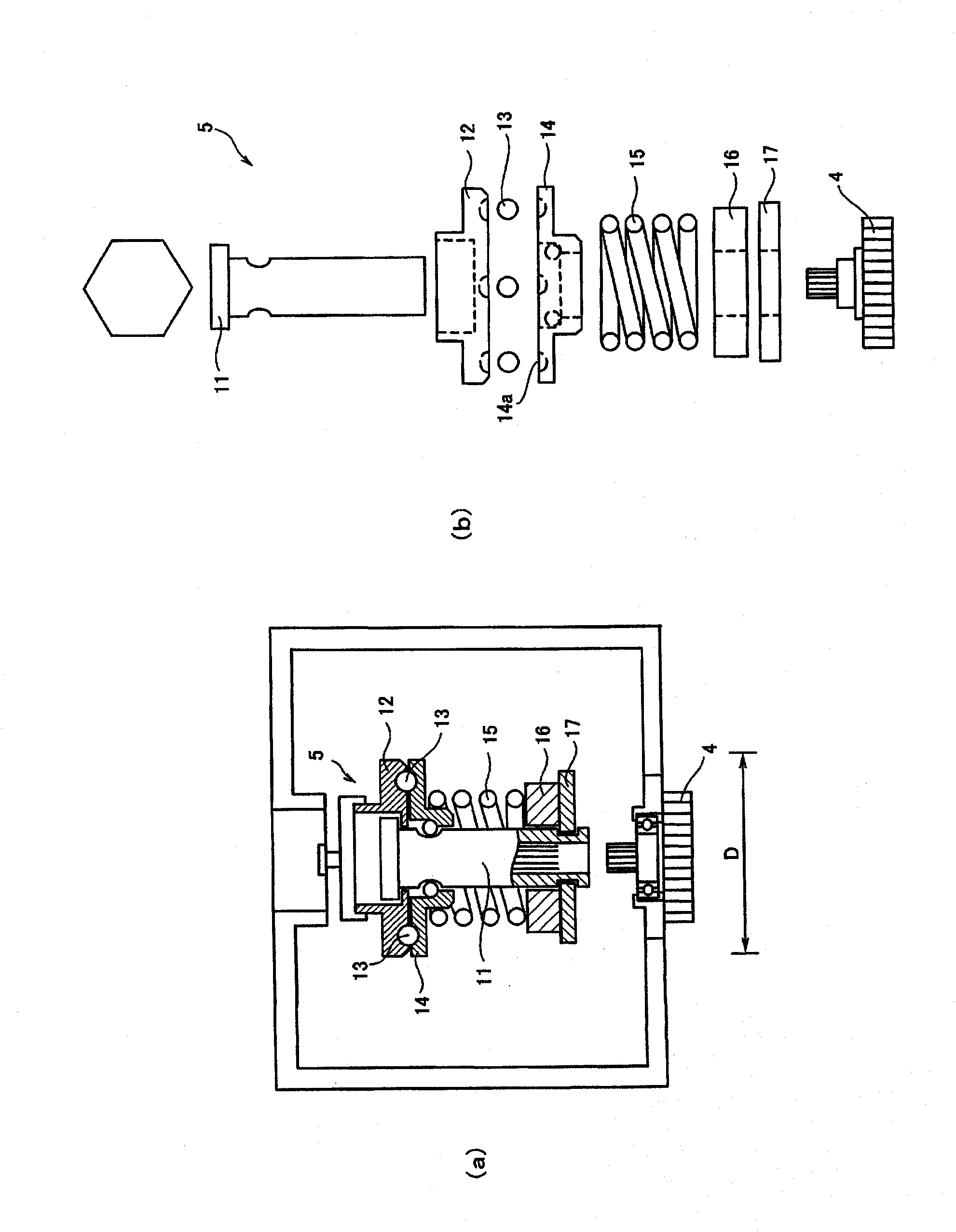
[0045] Embodiments of the present invention will be described below with reference to the drawings. here, figure 1 It is a brief side view of the screw fastening device of the first invention, figure 2 It is a brief top view of the screw fastening device of the first invention, image 3 It is an explanatory diagram of the clutch, Figure 4 is an explanatory diagram of the limit plate, Figure 5 This is an explanatory diagram of the operation of the displacement switch.

[0046] Such as figure 1 and figure 2 As shown, the screw fastening device of the present invention includes: a pistol-shaped device main body 1, a controller (not shown) that controls a direct current (DC) motor 3 constituting the device main body 1, a lithium ion battery (not shown) as a power source As shown in the figure), the cable 2 connecting the main body of the device 1 and the controller. The controller and the battery may be attached to a belt wrapped around the worker's waist, or may be ins...


PUM


Abstract

The present invention relates to a screw tightening device having a small-sized clutch, reduced in size and weight, and easily operable. A clutch (5) is directly connected to the output side of a DC motor (3), and as a result, the output of the DC motor (3) is less than the output of conventionally used motors. This reduces the size of the DC motor (3) and the clutch (5). Accordingly, the size and weight of a device body (1) are less than those of conventional products.

Description

technical field [0001] The present invention relates to a torque sensor capable of accurately and easily measuring a screw fastening device using an electric motor as a driving source and the fastening force on the driving side. Background technique [0002] As conventional screw fastening devices, there are angle type, pistol type, etc. Among them, there is known a screw fastening device having a structure in which a speed reducer is connected to the output side of the motor drive part, and a clutch is connected to the output side of the speed reducer. connected, and a socket tool is provided on the output side of the clutch (for example, refer to Patent Document 1). After tightening the screws, use a torque wrench to achieve the required tightening torque. [0003] As a mechanism for measuring the tightening axial force of a screw (bolt) to a fastened object, a strain gauge is installed between the screw and the fastened object on a bridge, etc. , There are built-in torq...

Claims


Application Information

Patent Timeline
Patent Type & Authority Applications(China)
IPC IPC(8): B25B21/00B25B23/14G01L3/14
CPCB25B23/14B25B23/141B25B21/00
Inventor 河村修治境秀树间山英城竹熊秀史
Owner HONDA MOTOR CO LTD
Why Eureka
Try Eureka