Overcurrent-tripping device for circuit breaker

A technology of tripping device and circuit breaker, applied in circuits, emergency protection devices, electrical components, etc., can solve the problems of difficulty in ensuring the stability of overcurrent tripping action and the reduction of the compressive strength of the casing, and achieve stable fixed support and eliminate withstand voltage. The effect of reducing the strength and securing the action characteristics

Inactive Publication Date: 2010-06-23
FUJI ELECTRIC FA COMPONENTS & SYST CO LTD
View PDF1 Cites 0 Cited by
  • Summary
  • Abstract
  • Description
  • Claims
  • Application Information

AI Technical Summary

Problems solved by technology

Therefore, it is difficult to ensure a stable overcurrent trip operation of the circuit breaker corresponding to the trip current value set with the adjustment dial 15.
[0014] In addition, if bearing grooves are formed on the left and right side walls of the housing 1 in order to hold both ends of the shaft portion 13a of the adjustment link 13, there will be a problem that the side walls of the housing will be partially thinned, and the housing will become thinner. The compressive strength is reduced, or the shell side wall must be designed to be thicker than necessary

Method used


Image

  • Overcurrent-tripping device for circuit breaker
  • Overcurrent-tripping device for circuit breaker
  • Overcurrent-tripping device for circuit breaker

Examples


Embodiment Construction

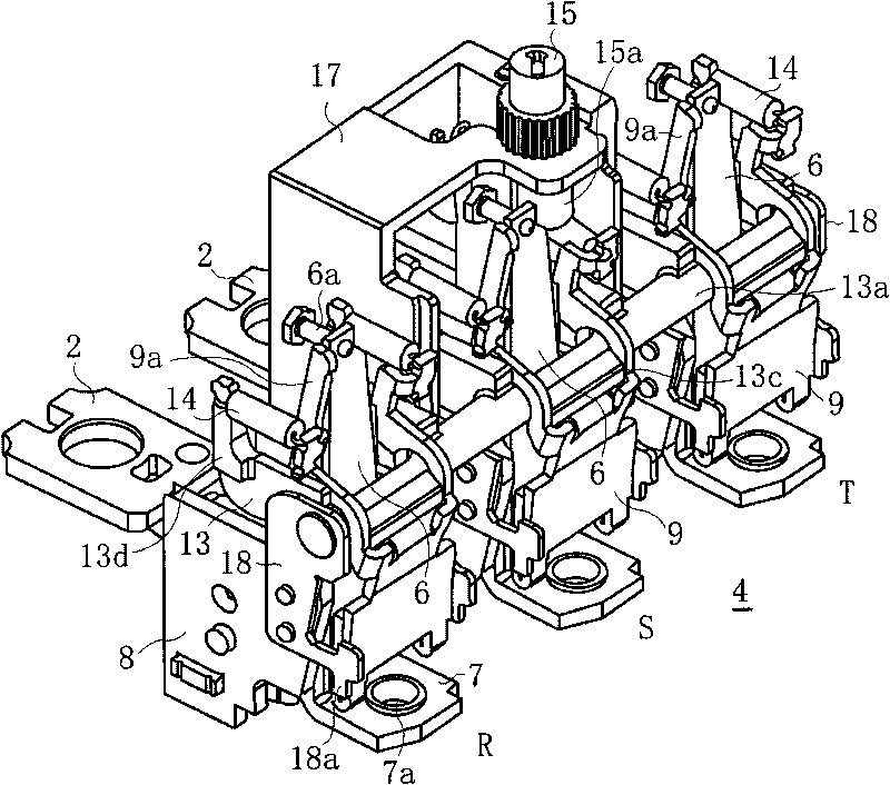
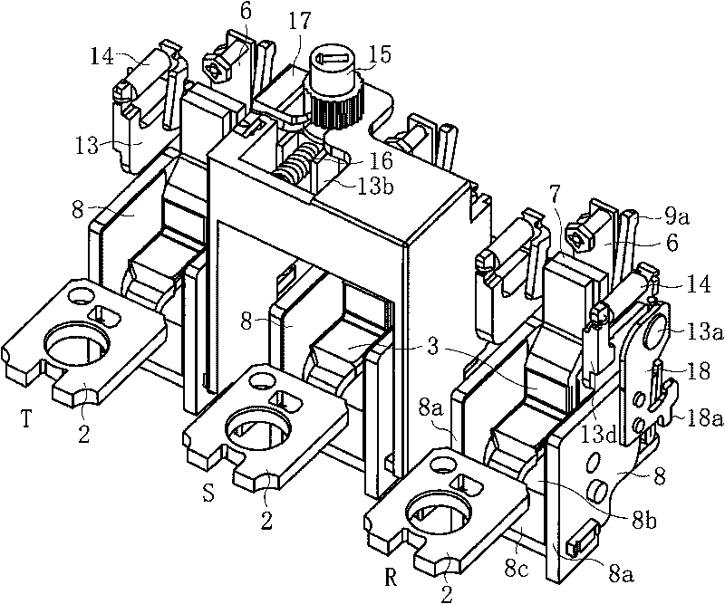
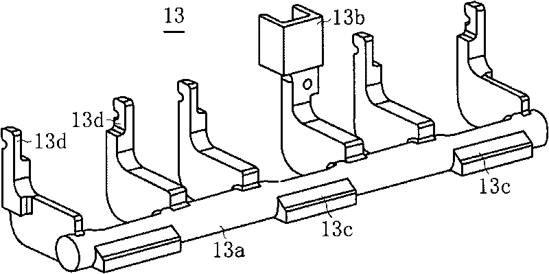
[0051] Below, according to Figure 1 to Figure 6 The examples shown illustrate embodiments of the invention. figure 1 It is a perspective view of the unit assembly of the current trip device viewed from the surface side, figure 2 It is a perspective view of the unit assembly of the current trip device viewed from the back side, image 3 It is the perspective view of the external shape of the adjustment connecting rod, Figure 4A and Figure 4B is the perspective view of the armature, Figure 5 is the structural diagram of the bottom of the case of the circuit breaker, Image 6 It is a cross-sectional view of the overall structure of a circuit breaker equipped with an overcurrent tripping device. Figure 7 , Figure 8 Corresponding components are marked with the same symbols.

[0052] In the following embodiments, although various limitations are made on constituent elements, types, combinations, shapes, relative arrangements, etc., these are merely examples, and the pr...


PUM


Abstract

The invention provides an overcurrent-tripping device for circuit breaker, which is capable of ensuring stable overcurrent-tripping feature and preventing lowering of the compressive strength of the housing by improving the assembly structure of a tripping current regulation mechanism. The overcurrent-tripping device for circuit breaker is constructed by a thermal tripping mechanism and an assembly body of the electromagnetic tripping mechanism. The thermal tripping mechanism is assembled with a bimetal (6) and a heating conductor (7), which are connected with an electricity supply path of a main circuit. The electromagnetic tripping mechanism is assembled with a magnetic yoke (8) surrounding the electricity supply path and supported on the heating conductor (7), and an armature (9) provided in the state of opposing the magnetic yoke (8). The armature (9) is kept on the shaft (13a) of the expansion link (13) in linkage with the adjusting dial (15) in a rotatable manner, a shaft bearing holding board (18) is embedded on both ends of the shaft (13a) of the expansion link (13), and the expansion link is directly born on the lateral wall of the magnetic yoke (8) through the shaft bearing holding board (18).

Description

technical field [0001] The present invention relates to a thermal-electromagnetic type overcurrent tripping device mounted on a circuit breaker such as a circuit breaker for wiring, and specifically relates to an assembly structure of an adjustment mechanism for setting an electromagnetic operating current. Background technique [0002] As an overcurrent tripping device for a circuit breaker, a device in the following manner is known: a thermal tripping mechanism with delay tripping characteristics and an electromagnetic tripping mechanism with instantaneous tripping characteristics are assembled, and the circuit breaker is arranged by operation. The adjustment dial on the cover side can variably adjust the electromagnetic operating current (for example, refer to Patent Document 1). [0003] The thermal-electromagnetic overcurrent tripping device connects the armature (armature, movable iron piece) of the electromagnetic tripping mechanism with the adjustment dial, which is ...

Claims


Application Information

Patent Timeline
Patent Type & Authority Applications(China)
IPC IPC(8): H01H71/40
CPCH01H71/02H01H71/123H01H71/24H01H2300/042
Inventor 佐藤佑高浅川浩司浜田佳伸
Owner FUJI ELECTRIC FA COMPONENTS & SYST CO LTD
Why Eureka
Try Eureka