Fastening device, casing using same, and fastening method

A technology for fasteners and fastening parts, which is applied to the installation of fixing devices, connecting components, and support structures, etc., to achieve the effect of easy fastening operations

Inactive Publication Date: 2014-01-08
FUJITSU LTD
View PDF5 Cites 0 Cited by
  • Summary
  • Abstract
  • Description
  • Claims
  • Application Information

AI Technical Summary

Problems solved by technology

Such a problem occurs not only in the fastening work of the column member and the cross member, but also in the fastening of multiple parts.

Method used


Image

  • Fastening device, casing using same, and fastening method
  • Fastening device, casing using same, and fastening method
  • Fastening device, casing using same, and fastening method

Examples


Embodiment

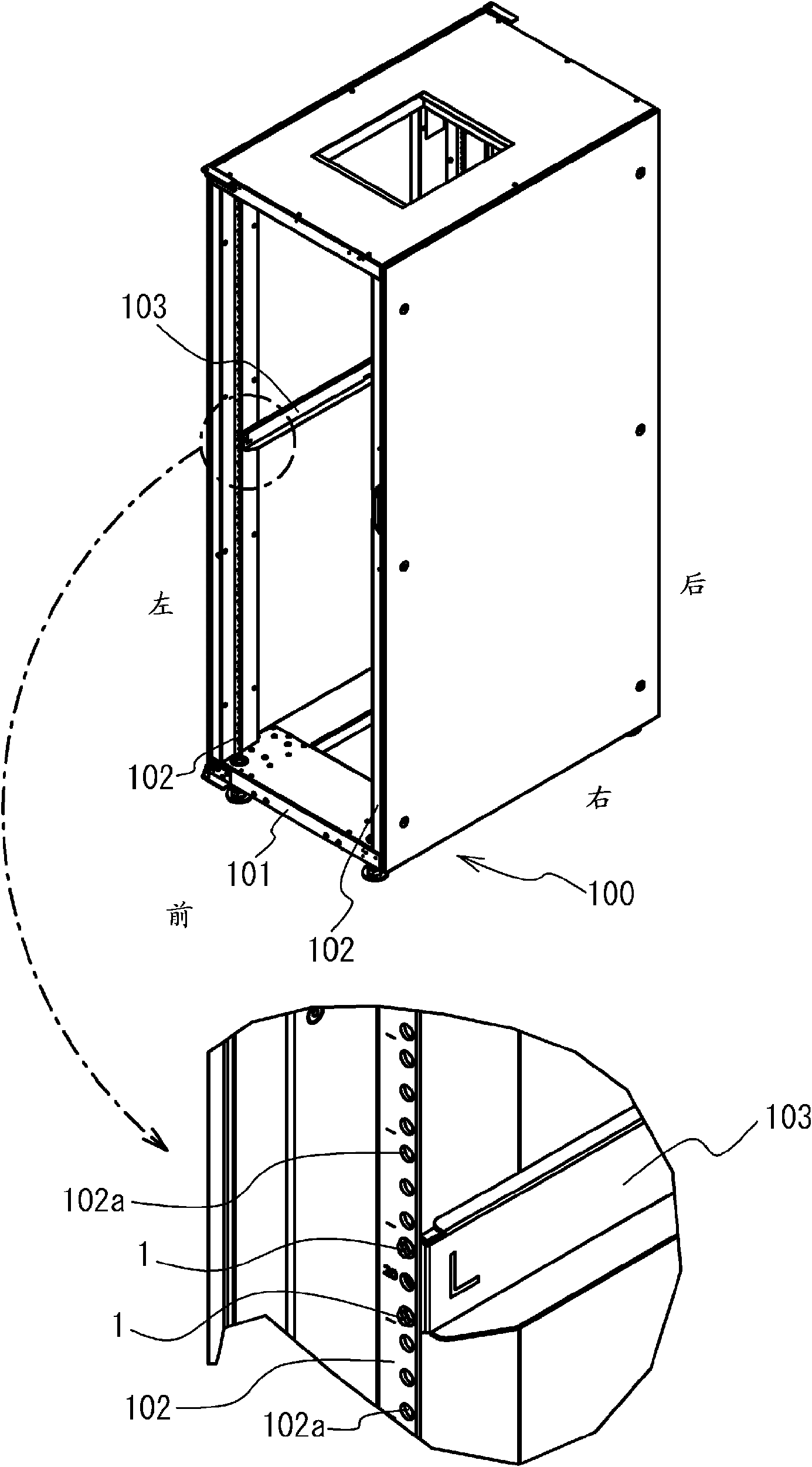
[0021] figure 1 It is a perspective view of a rack device 100 as an example of a casing. The rack device 100 includes a plurality of column members 102 erected on the base portion 101 . A horizontal bar member 103 extending in the horizontal direction is fastened to the column member 102 . The column member 102 and the cross bar member 103 are fastened in an overlapping state. Electronic devices such as servers are installed on the cross member 103 fastened to the column member 102 . In addition, for ease of description, in the following description, as figure 1 The front, rear, left and right of the rack unit 100 are defined as shown.

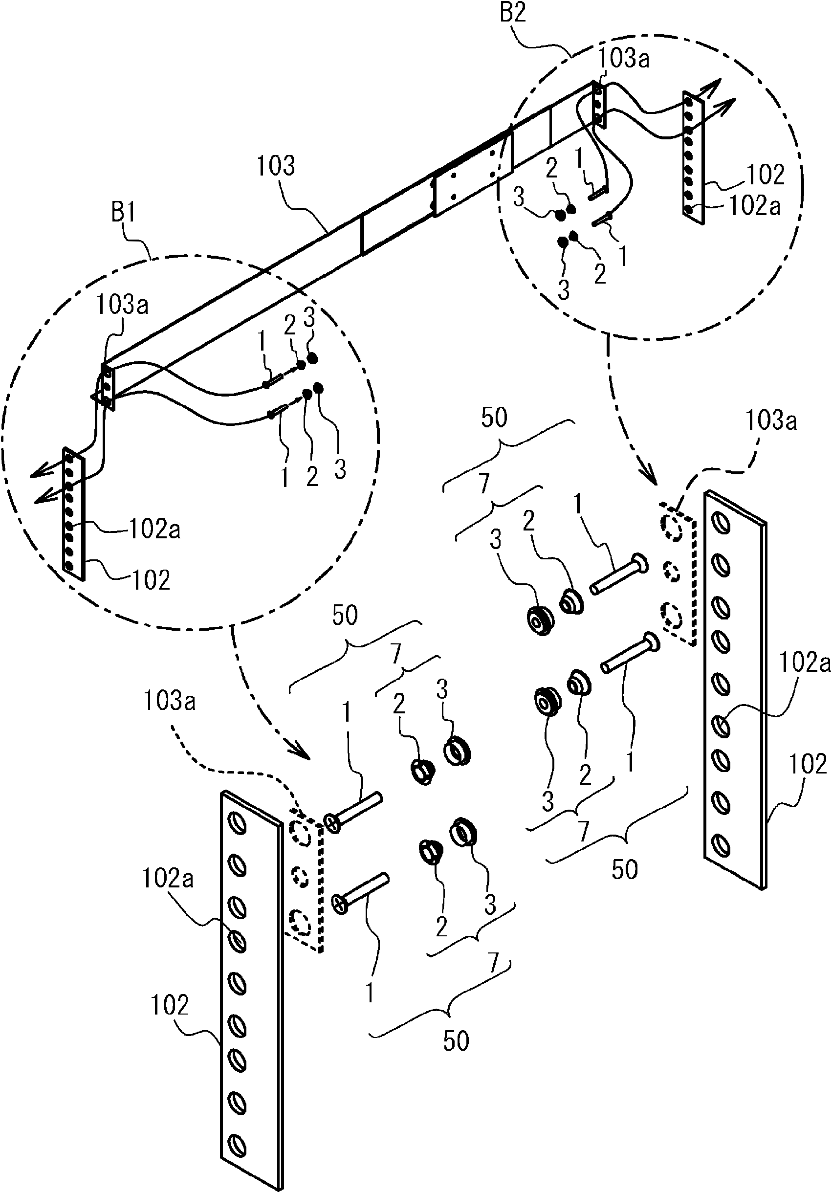
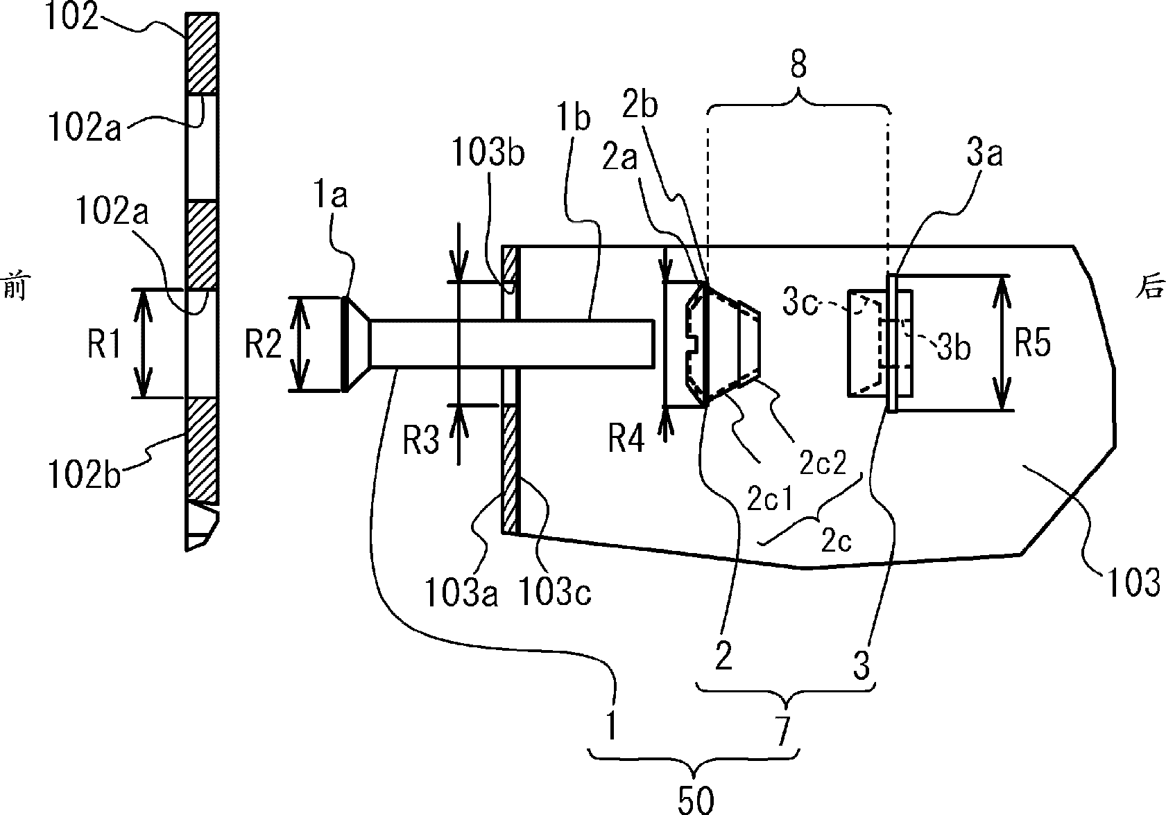
[0022] figure 2 It is a perspective view showing the column member 102 and the cross member 103 before fastening. like figure 2 , image 3 As shown, fasteners 50 are used in fastening the column member 102 to the rail member 103 . image 3 It is an explanatory diagram showing the state of the fastener 50 before pre-tightening.

[0...


PUM


Abstract

It is an object to facilitate a fastening operation of plural members so as to enable an operator to do the fastening work. A fastening device 50 includes: a screw member 1 penetrated through attachment holes; and a fastening member holding portion 7. The fastening member holding portion 7 includes; a first surface engagement portion 2a that is located at a first surface 102b side of the plural overlapped members (102 and 103), and that is engaged with the first surface 102b; an extension portion 2c that extends from the first surface engagement portion 2a to a second surface 103c side as a rear side of the first surface 102b; a second surface engagement portion 3c that is located at the second surface 103c side, and that is engaged with the second surface 103c; and a screw portion 3b that moves the second surface engagement portion 3c to the first surface engagement portion 2a side in response to rotation of the screw member 1. The fastening member holding portion 7 brings the members (102 and 103) into a temporary fastened state, and the fastening device 50 brings the members (102 and 103) into a final fastened state.

Description

technical field [0001] The present invention relates to a fastener, a housing using the same, and a fastening method. Background technique [0002] When assembling a case or a rack device on which an electronic device is mounted, a horizontal bar member arranged in the horizontal direction may be fastened between vertically arranged column members. Conventionally, it has been proposed to improve the fastening between such a column member and a cross member (see Patent Document 1). Furthermore, a plate anchor is proposed that can be used for fastening such a column member and a cross member (see Patent Document 2). [0003] Patent Document 1: Japanese National Publication No. 2007-507862 [0004] Patent Document 2: Japanese Patent Application Publication No. 1-124411 [0005] However, when fastening a column member and a cross bar member, the head of the bolt used for fastening is generally located in the outer side of a column member. For example, press the bar member in...

Claims


Application Information

Patent Timeline
Patent Type & Authority Patents(China)
IPC IPC(8): F16B1/02F16B5/02F16B13/04F16B13/06
CPCH05K7/1489F16B5/02Y10T29/49948F16B1/02F16B13/04F16B13/06
Inventor 岩崎史宣
Owner FUJITSU LTD
Why Eureka
Try Eureka