Engine

An engine and transmission technology, applied in the direction of engine components, machines/engines, mechanical equipment, etc., can solve problems such as restricting the miniaturization of engines and poor workability, and achieve improved assembly and maintenance, as well as improved assembly and maintenance. , The effect of easy installation and disassembly

Inactive Publication Date: 2010-01-06
HONDA MOTOR CO LTD
View PDF10 Cites 0 Cited by
  • Summary
  • Abstract
  • Description
  • Claims
  • Application Information

AI Technical Summary

Problems solved by technology

[0004] In this conventional engine, as disclosed in Patent Document 1, the cylinder head is formed such that the outer end surface on which the operation window is opened reaches the axially outer side of the driven rotation member, so that the driven rotation member is arranged inside the operation window, thus As a result, the work of attaching the ring-shaped transmission member to the driven rotary member and the camshaft is hindered by the cylinder head around the driven rotary member, resulting in poor workability
In addition, the cover body joined to the outer end surface of the cylinder head must have a large distance from the driven part in the axial direction as a whole, which restricts the miniaturization of the engine.

Method used


Image

  • Engine
  • Engine
  • Engine

Examples


Embodiment 1

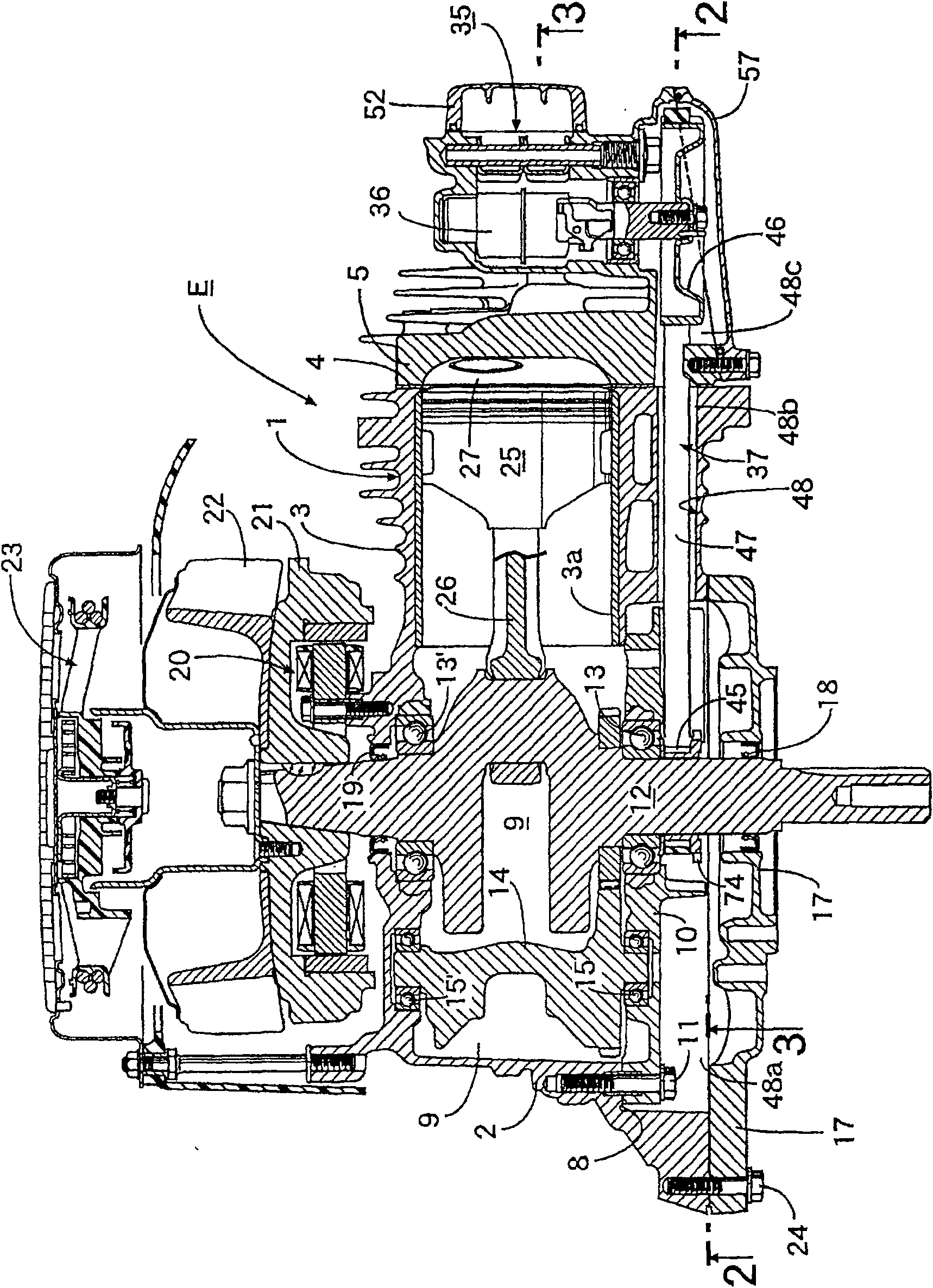
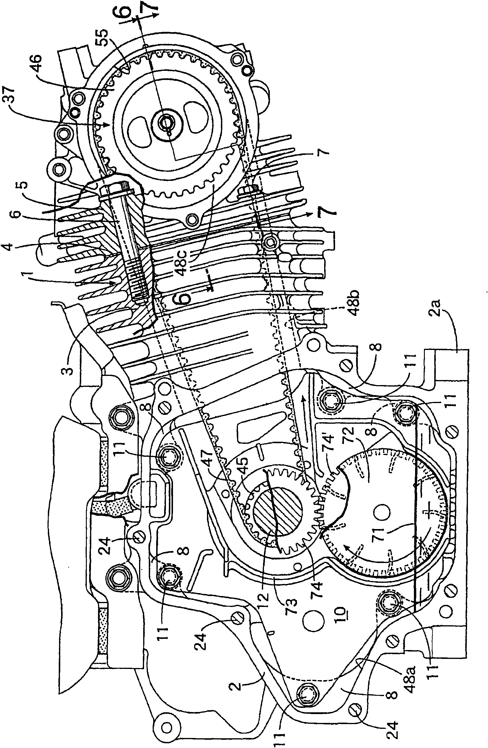
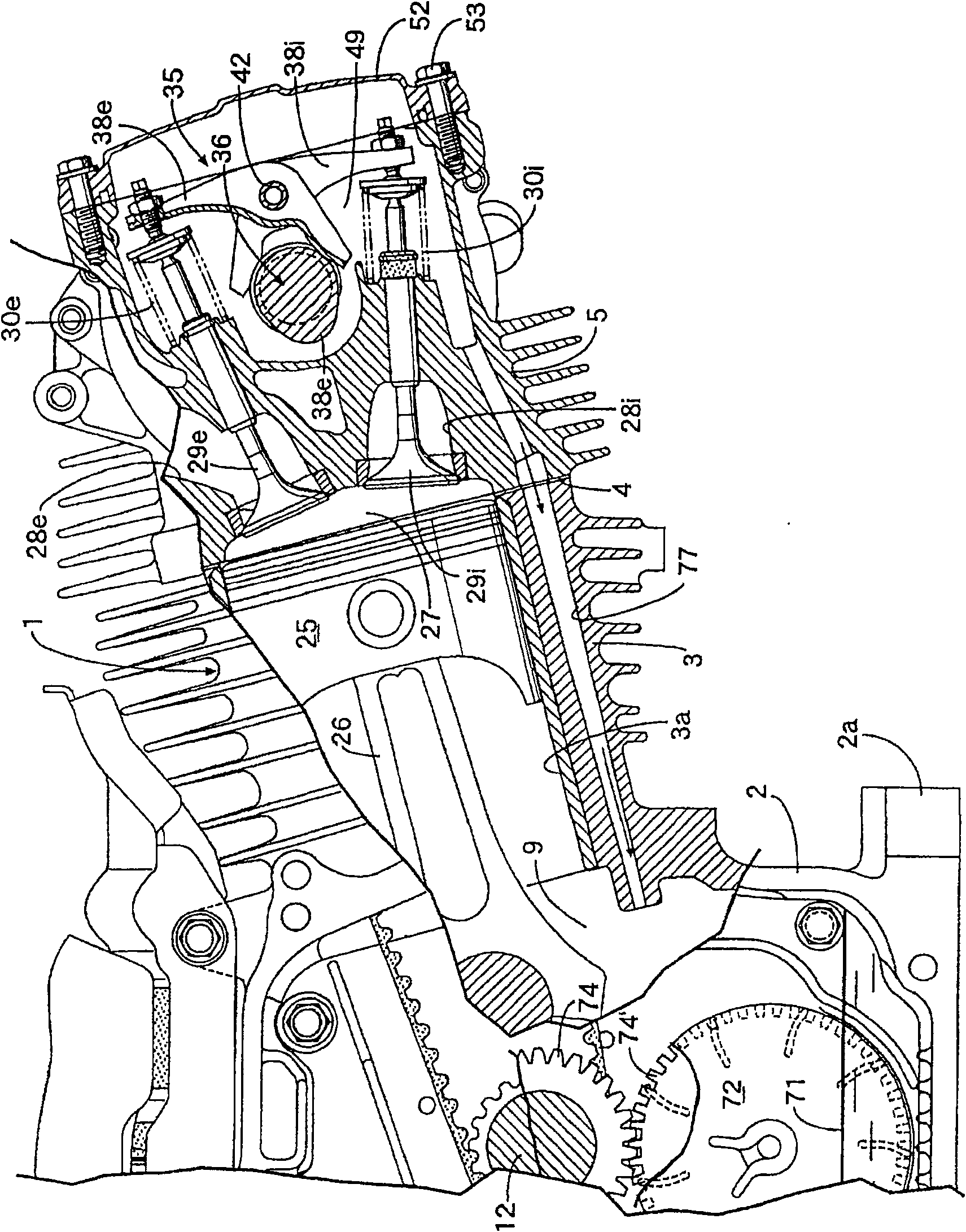
[0039] First, in Figure 1 ~ Figure 4 Among them, the constituent elements of the engine main body 1 of the general-purpose four-stroke engine E include: a crankcase 2 having a mounting seat 2a at the bottom; a cylinder block 3 integrally connected with the crankcase 2 and having an upwardly inclined cylinder bore 3a; The cylinder head 5 to which the gasket 4 is joined to the upper end of the cylinder block 3 is fastened using four main fastening bolts 6 arranged at four positions around the cylinder bore 3 a. 6... and two auxiliary connecting bolts 7, 7 described later.

[0040] The crankcase 2 has one side open, and a plurality of stepped portions 8, 8... are integrally formed on the inner peripheral wall slightly inward from the open surface, facing the open surface side and juxtaposed in the circumferential direction. The bearing bracket 10 is fixed on the parts 8, 8... by a plurality of bolts 11, 11.... Both ends of the crankshaft 12 in a horizontal posture are supporte...


PUM


Abstract

An engine where a crankshaft (12) and a camshaft (36) are connected by a timing transmission device (37) composed of a drive rotation member (45), a driven rotation member (46), and an endless transmission member (47), a working window (55) for attaching and detaching the driven rotation member (46) to and from the cam shaft (36) is opened in an outer end surface (5c) of a cylinder head (5), and a lid body (57) for closing the working window (55) is joined to the outer end surface. The outer end surface (5c), to which the lid body (57) is joined, of the cylinder head (5) is the inclined surface (5c) inclined such that that outer peripheral section of the driven rotation member (46) which is on the opposite side of the drive rotation member (45) is exposed from the working window (55). The construction improves workability in installation of the endless transmission member on the driven rotation member, installation of the driven rotation member on the camshaft, etc., and in addition, the construction contributes to downsizing of the engine.

Description

technical field [0001] The present invention relates to an improvement of an engine which connects between a crankshaft supported on a crankcase and a valve drive camshaft supported on a cylinder head by a timing transmission consisting of a drive rotating member fixed to the crankshaft, It consists of a driven rotating part fixed to the camshaft and an annular transmission part wound on these two rotating parts. A work window for the driven rotating part to be disassembled from the camshaft is provided on one side of the cylinder head. A cover body for closing the work window is also joined to the cylinder head. Background technique [0002] The above-mentioned engine is known as disclosed in Patent Document 1. [0003] Patent Document 1: Japanese Patent Application Laid-Open No. 10-54296 [0004] In this conventional engine, as disclosed in Patent Document 1, the cylinder head is formed such that the outer end surface on which the operation window is opened reaches the a...

Claims


Application Information

Patent Timeline
Patent Type & Authority Patents(China)
IPC IPC(8): F02F7/00F01L1/04F01L1/46F02B63/00F02B63/04F02B67/06F02F1/00
CPCY10T29/49826F01L2103/00F02B75/16F02B67/06F01L1/182F01L2001/0535F01L1/024F01L2303/00
Inventor 河野昌平桥本学本田宗平
Owner HONDA MOTOR CO LTD
Why Eureka
Try Eureka