Optical modulator
A technology of optical modulators and modulators, applied in optics, instruments, electromagnetic transmitters, etc., can solve the problems that the signal part cannot obtain the waveform shaping effect, and the level of the signal cannot be consistent with the valley of the modulation characteristic, so as to improve the receiving sensitivity , expand the eye aperture, and efficiently transmit information
- Summary
- Abstract
- Description
- Claims
- Application Information
AI Technical Summary
Problems solved by technology
Method used
Image


Examples
Embodiment 1
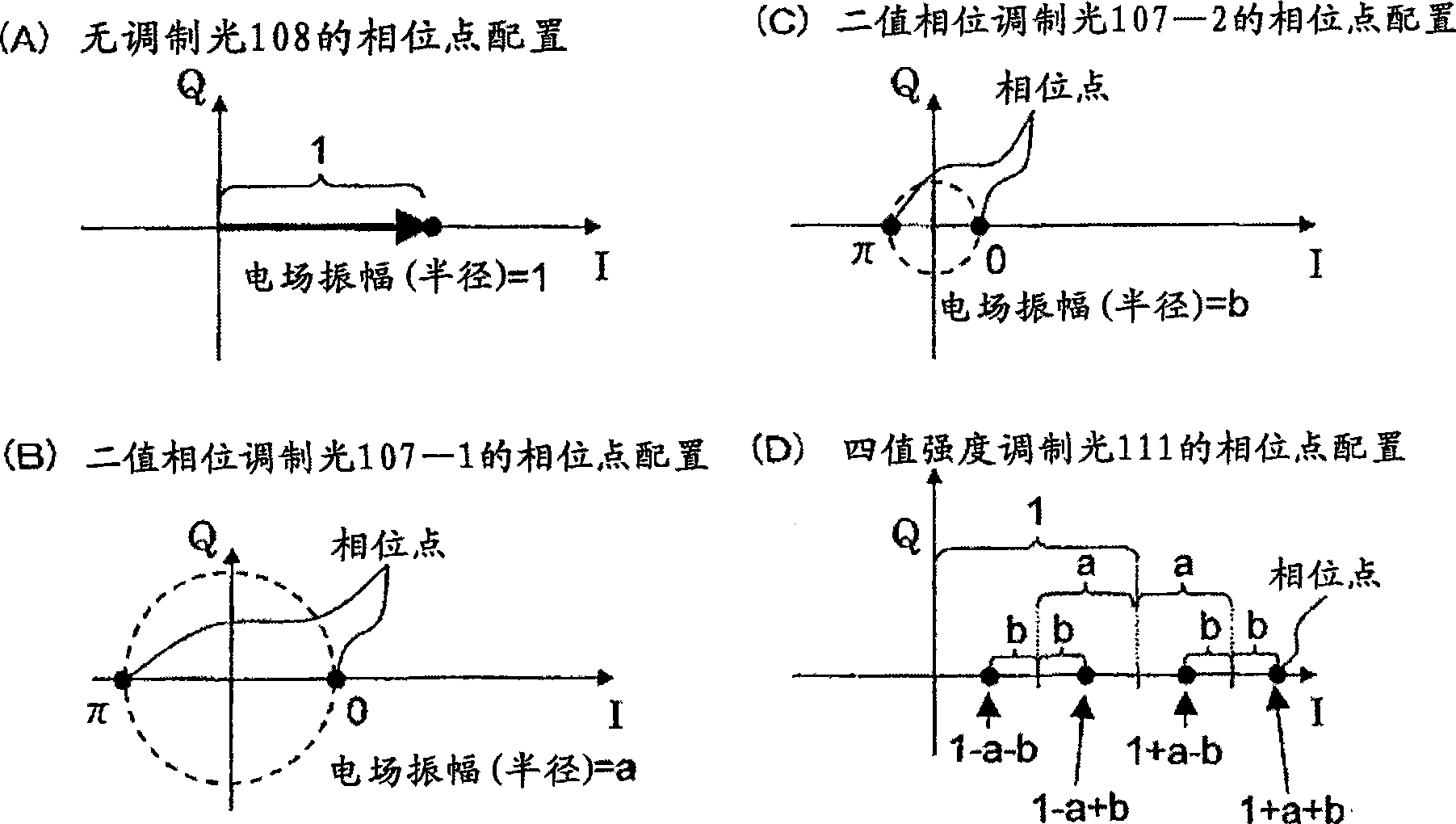
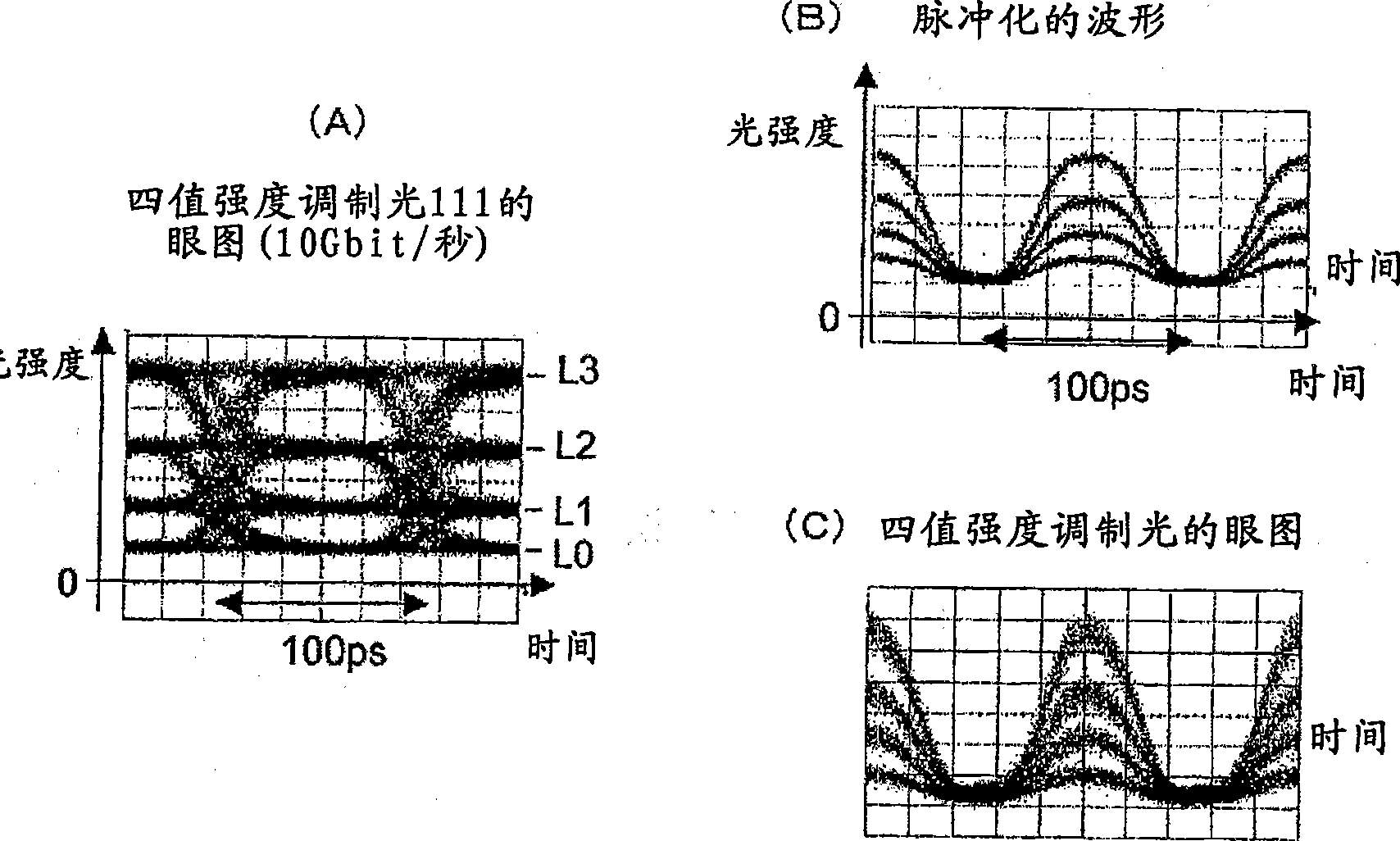
[0093] figure 1 As a first embodiment of the present invention, a quaternary optical amplitude modulator 100 is shown.
[0094] The input light 101 provided from the input optical path 102 is branched into a first optical path 104-1, a second optical path 104-2, and a third optical path 104-3 by the optical splitter 103. Among these optical paths, in the second optical path 104-2 and the third optical path 104-3, single-phase MZ-type binary optical phase modulators 105-1 and 105-2 are arranged respectively, and in the first optical path In 104-1 and the third optical path 104-3, optical phase adjusters 106-1 and 106-2 are arranged respectively.
[0095] Separate electrical digital signals are respectively applied to the modulation signal input terminals 112 - 1 , 112 - 2 of the binary optical phase modulators 105 - 1 , 105 - 2 . These telecommunication code rates are the same, and the amount of signal delay is adjusted so that the bit timings coincide with each other. As a...
Embodiment 2
[0120] As a second embodiment of the present invention, Figure 13 A quaternary optical amplitude modulator 100A having an automatic phase adjustment function is shown.
[0121]When the length of each optical path connected to the optical coupler 109 changes, for example, due to a change in ambient temperature or a change over time, the size of the eye aperture of the multivalued light intensity modulation waveform output from the optical coupler 109 changes. , the transmission characteristics deteriorate. When the eye aperture changes greatly, the logic value of the digital signal is inverted, and signal transmission may not be possible. At this time, each phase point also changes in the phase direction, and there is a possibility that transmission deterioration due to waveform chirp may occur, or a large deterioration may also occur in the phase modulation result.
[0122] In the second embodiment, in order to prevent these phenomena, a part of the output light 111 of the ...
Embodiment 3
[0137] As a third embodiment of the present invention, Figure 15 A configuration example of the octal optical amplitude / phase modulator (amplitude binary, phase quaternary) 200 is shown. In this embodiment, the binary optical amplitude modulator 153 which is the basic form of the present invention is used.
[0138] The unmodulated light 151 output from the semiconductor laser light source 150 is input to a well-known quadrature quaternary optical phase modulator (QPSK) 133, and converted into quadrature quaternary phase modulated light 152-1. The quadrature quaternary phase modulated light 152-1 is input to the binary optical amplitude modulator 153, and undergoes chirp-free binary amplitude modulation. Inside the binary optical amplitude modulator 153, the input quadrature optical phase-modulated light 152-1 is branched into a first optical path 104-1 and a second optical path 104-2. The input light of the first optical path 104 - 1 is input into the optical coupler 109 wi...
PUM
 Abstract
Description
Claims
Application Information
 - R&D
- Intellectual Property
- Life Sciences
- Materials
- Tech Scout
- Unparalleled Data Quality
- Higher Quality Content
- 60% Fewer Hallucinations
Browse by: Latest US Patents, China's latest patents, Technical Efficacy Thesaurus, Application Domain, Technology Topic, Popular Technical Reports.
© 2025 PatSnap. All rights reserved.Legal|Privacy policy|Modern Slavery Act Transparency Statement|Sitemap|About US| Contact US: help@patsnap.com