
Online fault monitoring system for power transformer

A technology for power transformers and monitoring systems, applied in directions such as ultrasonic/sonic/infrasonic generation, can solve problems such as unsatisfactory gas selectivity, poor linearity, and large errors

Inactive Publication Date: 2009-08-05
SHANGHAI JIAO TONG UNIV
View PDF0 Cites 30 Cited by
  • Summary
  • Abstract
  • Description
  • Claims
  • Application Information

AI Technical Summary

Problems solved by technology

However, the above-mentioned online monitoring systems all have their Achilles heel
The sensor-based online monitoring system has poor linearity and is not ideal for gas selectivity, while the online monitoring equipment based on chromatographic analysis, due to the use of consumable devices such as chromatographic columns in the instrument, and most of the instruments also use gas-permeable membranes to obtain gas Oil and gas separation is carried out in the same way, and the carrier gas is also used in the monitoring process, resulting in the bulky size of the whole set of instruments, high cost, and frequent maintenance and updating of components, which brings a lot of trouble to the power workers.
However, the online monitoring equipment based on Fourier transform infrared spectroscopy cannot detect the important characteristic gas H 2 At the same time, when the gas concentration is too low, the infrared light intensity transmitted through the sample and the gas concentration still have nonlinear problems, and the error caused by light scattering and reflection is relatively large

Method used


Image

  • Online fault monitoring system for power transformer
  • Online fault monitoring system for power transformer

Examples


Embodiment Construction

[0022] The embodiments of the present invention are described in detail below in conjunction with the accompanying drawings: this embodiment is implemented on the premise of the technical solution of the present invention, and detailed implementation methods and specific operating procedures are provided, but the protection scope of the present invention is not limited to the following the described embodiment.

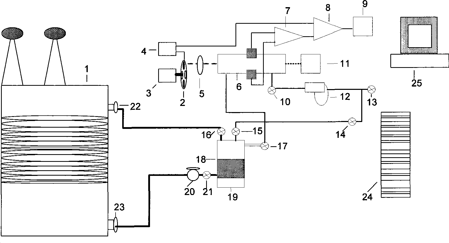
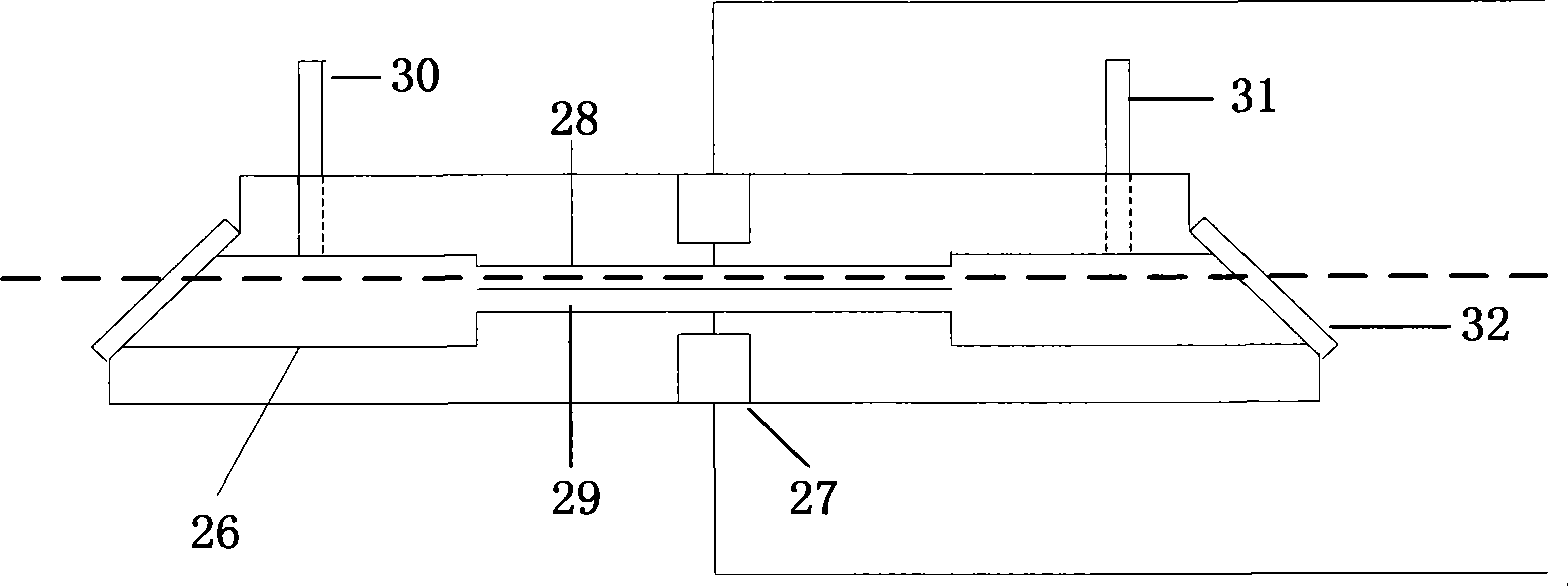
[0023] like figure 1 As shown, this embodiment includes: transformer 1, tunable cascaded diode laser 2, stepper motor 3, diode laser power controller 4, convex lens 5, photoacoustic cavity 6, differential amplifier 7, lock-in amplifier 8, data acquisition Card and digital recorder 9, laser power meter 11, electric vacuum pump 12, oil-gas separation chamber 18, ultrasonic oscillator 19, oil return pump 20, PLC controller 24, computer 25.

[0024] The oil-gas separation chamber 18 is located at the bottom of the whole system. Its oil inlet is connected to the oil valve...


PUM


Abstract

The invention relates to an online fault photoacoustic and spectroscopic monitoring system for a power transformer in the technical field of power engineering, comprising 7 tunable cascaded diode lasers, a gas and oil separating room, an optical-acoustic chamber, a lock-in amplifier, a power supply controller of the tunable cascaded diode lasers, a difference amplifier, a convex lens, a laser power meter, a digital recorder, an oil feed-back pump, an electric vacuum pump, a PLC and a computer. Ultrasonic degasification separation is performed for an oil sample in the gas and oil separating room, and fault gas is infused in the optical-acoustic chamber, after being directly modulated, a power supply can generate periodic vibration under the action of an infrared beam, thereby exciting to form a sound wave signal. After being detected by a rheomicrophone, the sound wave signal can be magnified by the lock-in amplifier and then is input in the digital recorder, thus the power transformer can be judged whether the current running state is fine according to the numerical value displayed on the digital recorder. Meanwhile, the data can be transmitted to a remote computer in a wire and wireless communication way.

Description

technical field [0001] The invention relates to an online monitoring system in the technical field of electric power engineering, in particular to a set of online power transformer fault monitoring system. Background technique [0002] In recent years, the power industry has actively applied online monitoring technology, carried out condition-based maintenance, strengthened routine testing and comprehensive analysis of equipment, and eliminated some equipment hidden dangers in time, making the power supply reliability rate of the national power grid as high as 99.99% in 2001, but this is different from that of developed countries. There is still a big gap in power supply reliability. The failure of electrical equipment, especially the failure of power transformers, has always been the main factor that endangers the stable and safe operation of the power grid. Therefore, it is particularly important to conduct real-time online monitoring of the operating status of power tran...

Claims


Application Information

Patent Timeline
IPC IPC(8): G01N29/34
Inventor 贺绍鹏王侨华尹毅顾金
Owner SHANGHAI JIAO TONG UNIV
Learn More