
Method for manufacturing diesel engine connecting bar

A manufacturing method and technology for diesel engines, which are applied to connecting rods, mechanical equipment, shafts and bearings, etc., can solve problems such as short experience time, incorrect processing dimensions, and inability to ensure verticality requirements, achieve reasonable processing methods, improve quality and The effect of efficiency

Inactive Publication Date: 2009-08-05
KUNSHAN JIANGJIN MACHINERY
View PDF0 Cites 26 Cited by
  • Summary
  • Abstract
  • Description
  • Claims
  • Application Information

AI Technical Summary

Problems solved by technology

[0003] The above-mentioned method for manufacturing connecting rods has the following defects: 1. In the traditional process, the processing of the socket and the positioning bolt hole is processed separately. As we all know, the socket and the positioning bolt hole have a high verticality requirement, and processing according to the traditional process will cause It is because of the double clamping that the verticality requirements cannot be guaranteed
2. Each process in the traditional process uses the small head hole and the end faces of the large and small holes as the positioning reference. In this way, the workpiece is not completely positioned, and the freedom of rotation around the center of the small hole is not restricted. The phenomenon of workpiece looseness leads to incorrect processing dimensions
3. In the sixth process of the traditional process, heat treatment is not performed after cutting the bearing cap and the connecting rod body. When the connecting rod cover and the connecting rod body are cut off, the elapsed time is short and the stress is not fully released before transferring to the next process. Processing, will affect product quality

Method used


Image

  • Method for manufacturing diesel engine connecting bar
  • Method for manufacturing diesel engine connecting bar

Examples


Embodiment

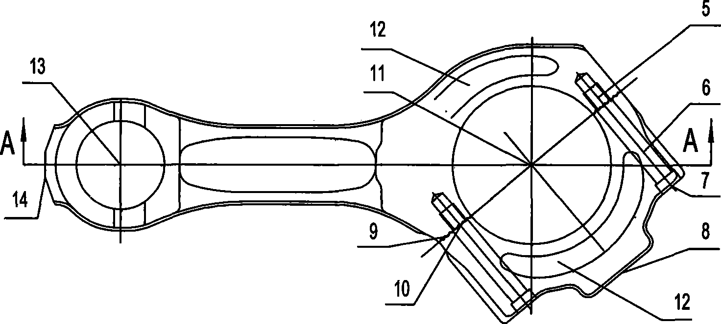
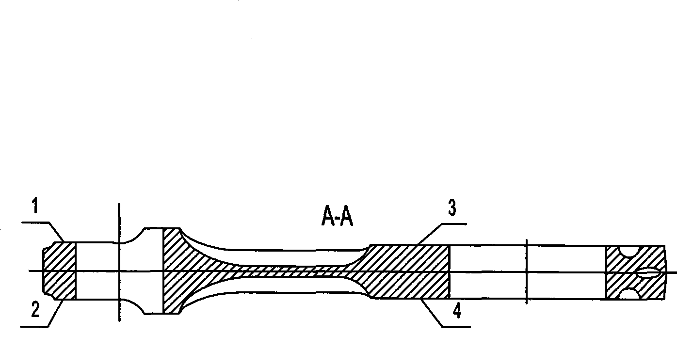
[0015] Example: see figure 1 , a kind of manufacturing method of diesel engine connecting rod, and its processing procedure comprises successively: 1), rough milling upper end face 3; Lower end face 4, expand and bore large hole 11, small hole 13; 3), cut off connecting rod body and bearing cover; 4), flaw detection; 5), stress relief treatment; 6), install connecting rod body and bearing cover, and The large hole 11, the small hole 13 and the lower end surface 4 are the positioning reference, and the upper end surface 3 is semi-finish milled; 7), disassemble the connecting rod body and the bearing cap, and repair the processing burrs; 8), check in the middle; 9), and the above end surface 3 is the positioning datum, mill the end face 14 of the bump of the connecting rod body and the half face 9 of the connecting rod body, extrude the threaded hole 5 on the half face 9 of the connecting rod body; 10), the above end face 3 is the positioning datum, mill the bearing cap Block e...


PUM


Abstract

The invention relates to a manufacturing method of a connecting bar of a diesel engine, which comprises the following processing steps: (1) roughly milling an upper end surface (3); (2) taking the upper end surface (3) as a positioning benchmark, correcting circular processing lines of a large hole (11) and a small hole (13); roughly milling a lower end surface (4); expanding the large hole (11) and the small hole (13), and the like. The manufacturing method is characterized in that in the step (10), the rough and precise counterboring of the flush socket (7) and the drilling, the expanding and the reaming of the bolt hole (6) are finished in one step; in the step (2) and the step (12), the large hole (11) and the small hole (13) are simultaneously half precisely bored, the sequential processing is positioned by the large hole (11), the small hole (13) and the upper end surface (3); in the step 22), plating protective layers positioned on the inner surfaces of the large hole (11) and the small hole (13) are chromium plating layers; in the step (23), the surface chemistry treatment adopts nitrogen treatment; and in the step (28), the surface layer strengthening treatment adopts shot blasting. The manufacturing method of a connecting bar of a diesel engine provided by the invention has reasonable step arrangement and can effectively enhance the quality and the efficiency of the processing of the connecting bar.

Description

technical field [0001] The invention relates to a method for manufacturing a connecting rod of a diesel engine, in particular to a method for manufacturing a connecting rod for a medium-speed marine diesel engine. Background technique [0002] There are 43 processes in the manufacturing and processing of traditional diesel engine connecting rods, which are as follows: 1. Roughly grinding the end face; 2. Drilling the small head hole; 3. Chamfering; 4. Pulling the small head hole; Block end face; 6, cutting off; 7, finish drawing both sides, joint surface and semicircle surface; 8, grinding joint surface; 9, middle inspection; 10, drilling bolt holes; 11, rough spot facing seat; ;13, milling the lock slot of the bearing bush; 14, chamfering and drilling oil hole; 15, deburring; Bolt positioning hole, hinge bolt positioning hole; 18, deburring; 19, cleaning; 20, installing bolts; 21, screwing the nut manually; 22, tightening the nut; 23, rough boring big hole; 24, chamfering;...

Claims


Application Information

Patent Timeline
IPC IPC(8): F16C7/02
Inventor 彭先虎彭瑜华陈飞
Owner KUNSHAN JIANGJIN MACHINERY
Learn More